Topics
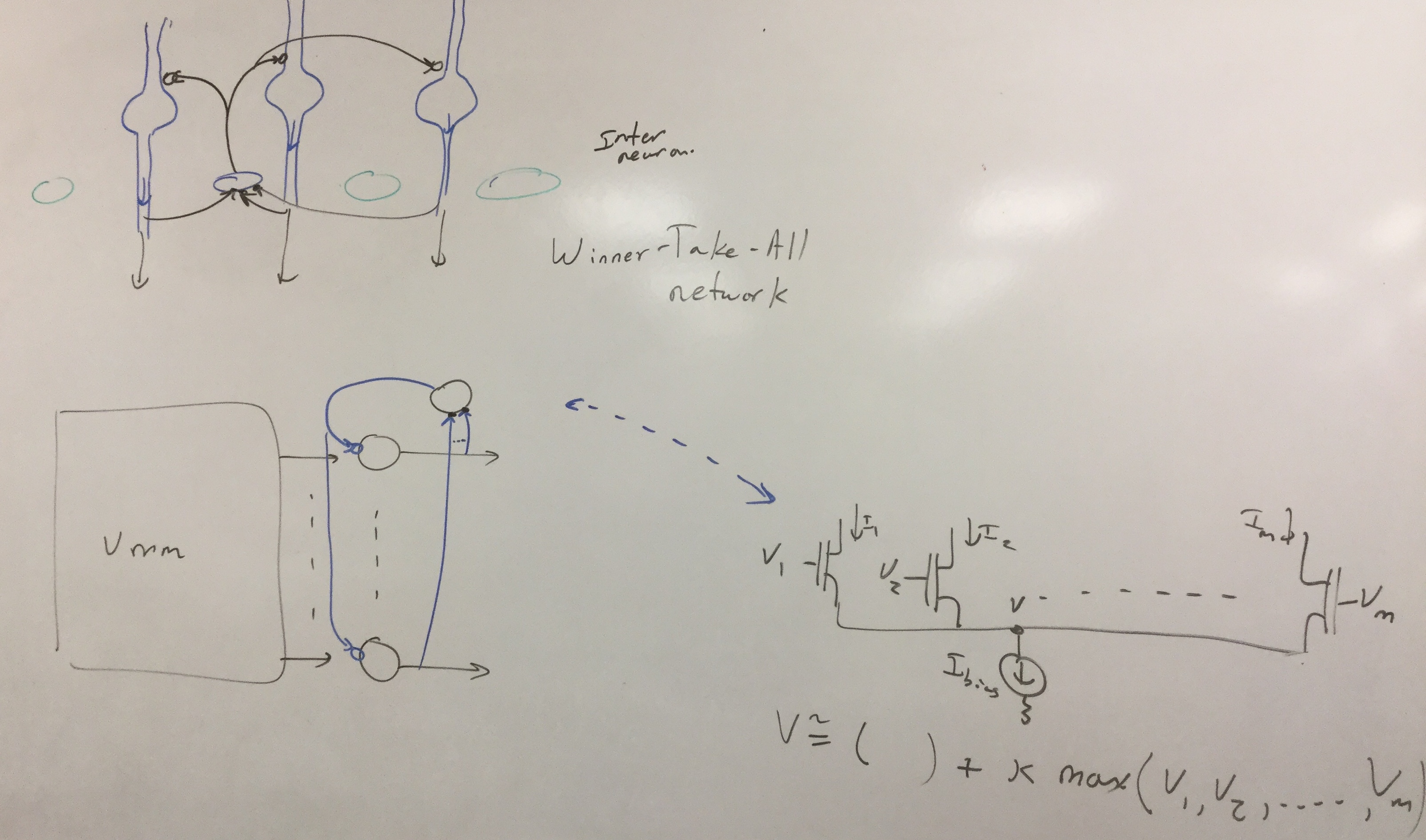
- Introduction to Winner-Take-All (WTA) Circuits
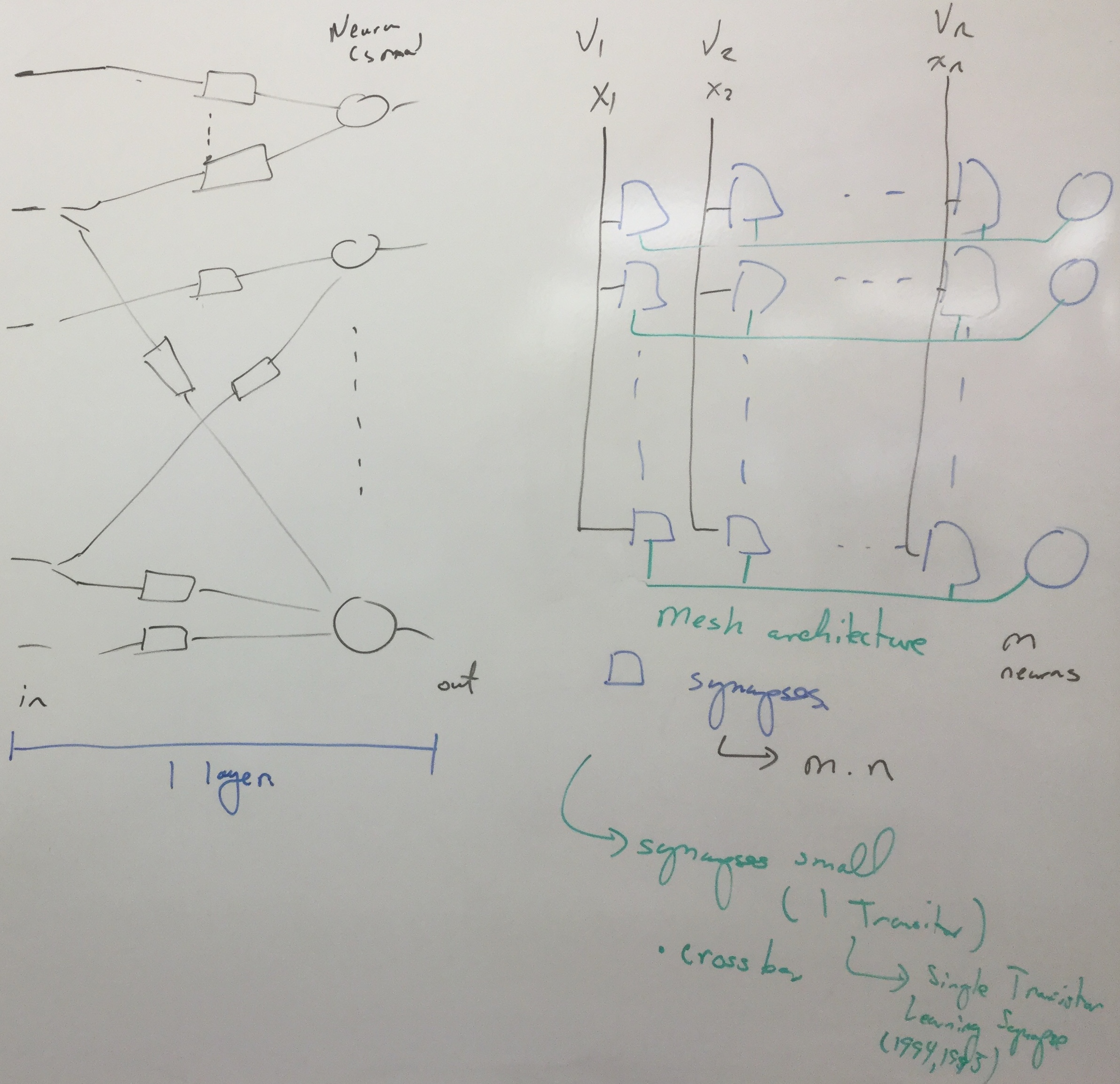
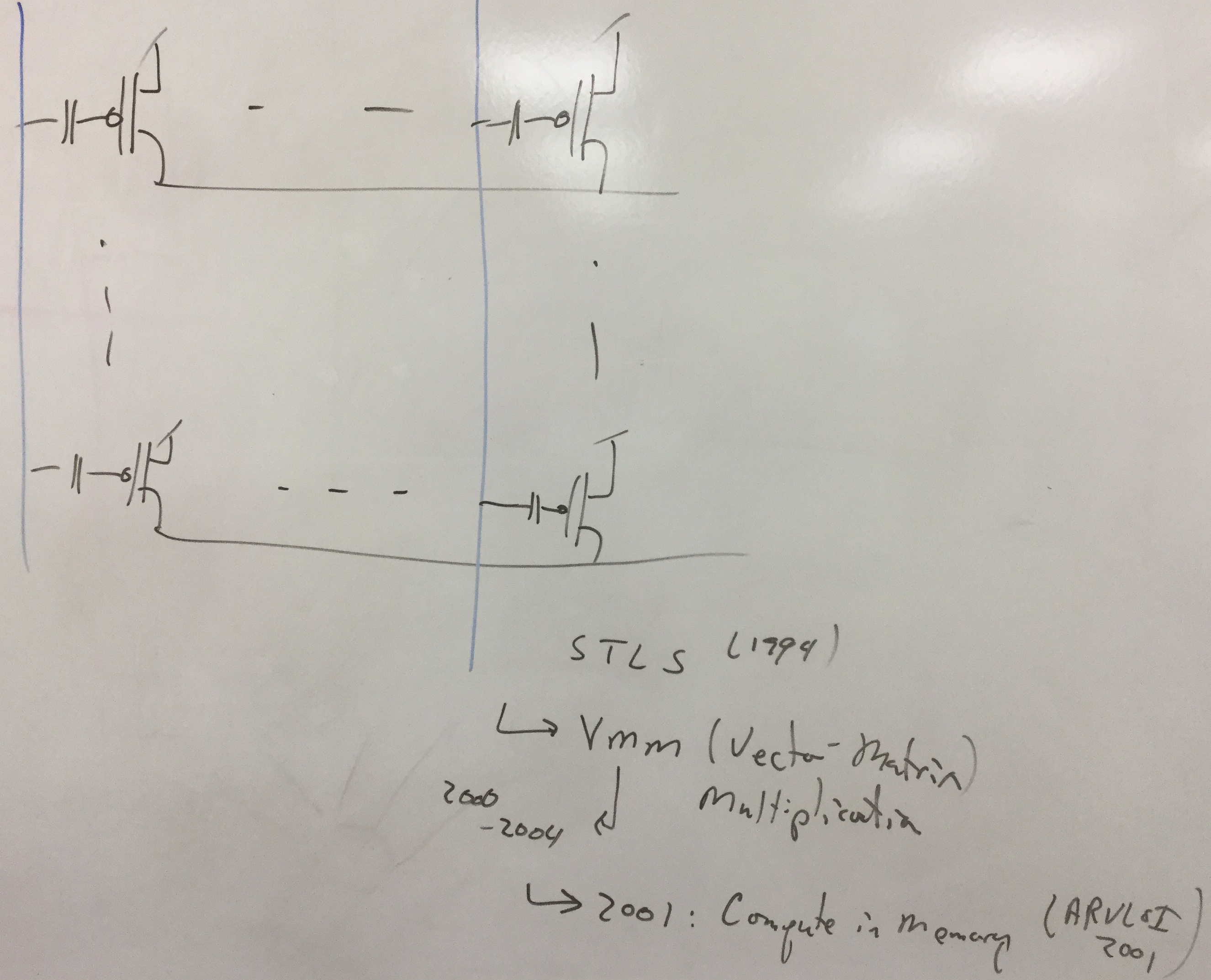
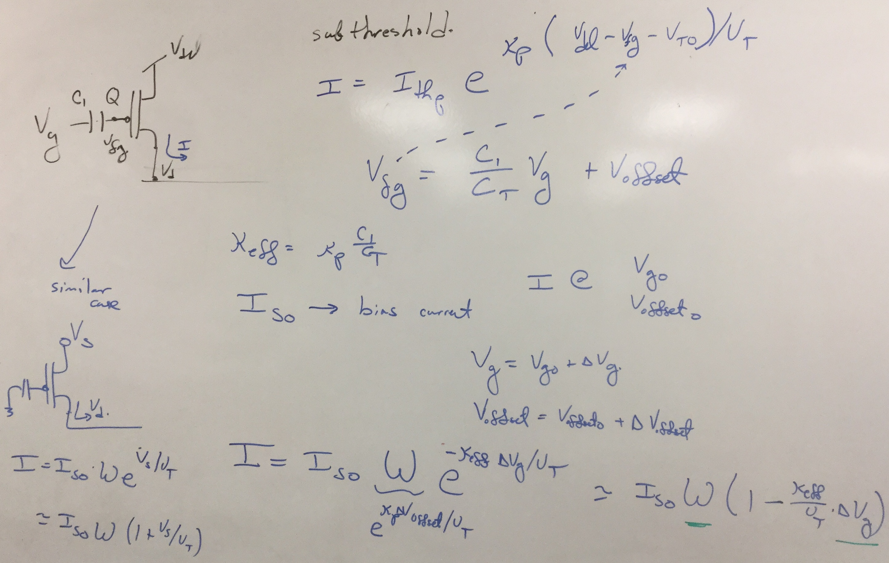
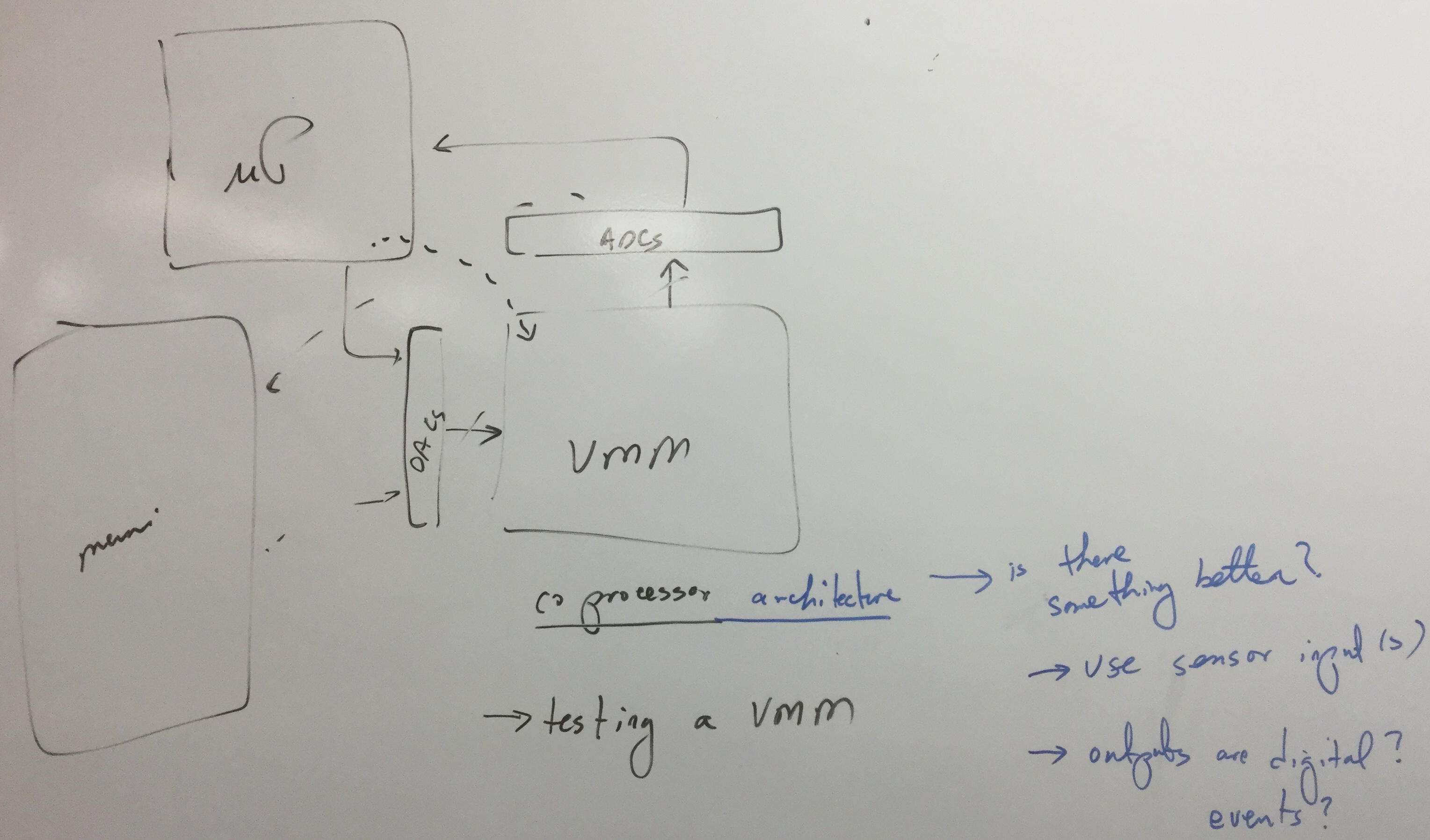
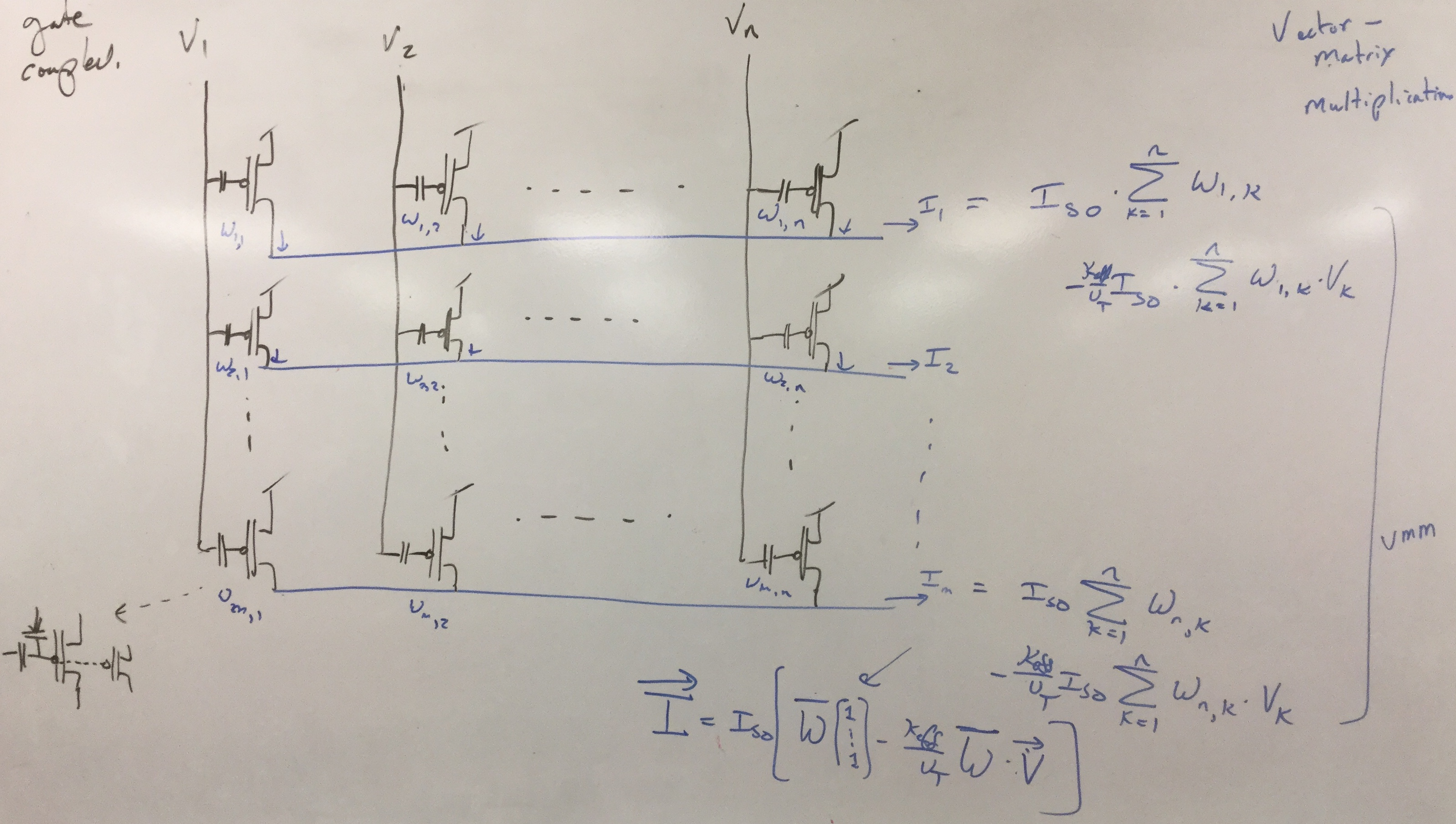
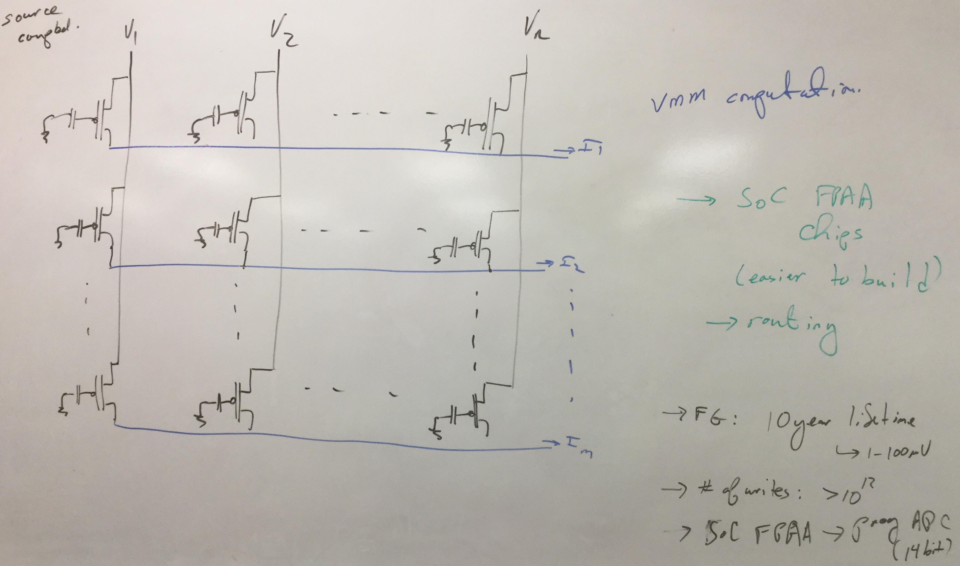
- Vector-Matrix Multiplication (VMM) Circuits
- Introduction to Classifiers
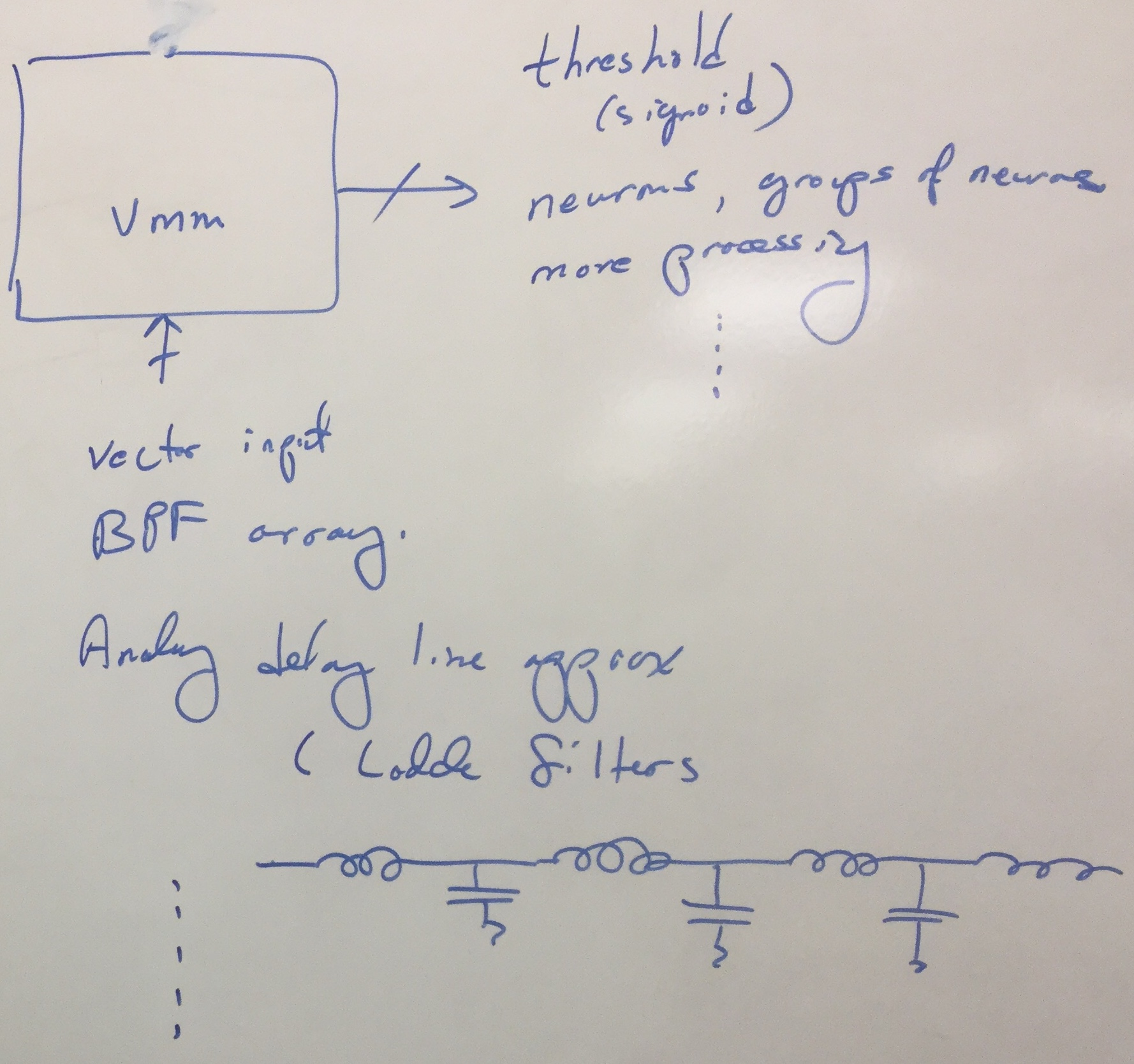
- VMM + WTA Classifiers
Class Schedule and Video Viewing
| Date | Class Topic | On-Line Lectures | Reading Material | White Boards |
| Feb 20 |
Neuroscience & Networks |
Sensor to Symbols, Manahattan Routing, FG VMM 01, Compute in Routing, Bio LTP Mechanism, | Learning on FPAA | 1 2 3 4 5 6 |
| Feb 22 |
VMM Circuits WTA Circuits VMM + WTA |
WTA Circuits, 2-Input WTA, VMM+WTA Classifier, VMM+WTA Mismatch, VMM+WTA Theory | 1 2 3 4 5 6 7 | |
| Feb 27 |
VMM+WTA Classifier | 1 2 3 4 | ||
| Feb 29 | Lab Discussion | . |
Reading Material
- Useful slides on Computation
- Original Paper on Winner-Take-All Circuits as well as the longer technical Report
- A more than necessary detailed overview on scanners
- For those who want to see an application of this circuit, which we will discuss more in a later section, I would recommend reading this paper. It also shows classification of multiple situations, showing experimentally the universal approximator behavior.
- Adaptive FG WTA which extends the Winner-Take-All concept to looking at largest changes in the inputs.
- Paper on Vector-Matrix Multiplication (VMM) Circuits compiled into an FPAA structure.
- As a reminder, the SoC FPAA paper has additional material that you have read previously.
- VMM + WTA Embedded Classifier and Learning pdf
WTA Overview:
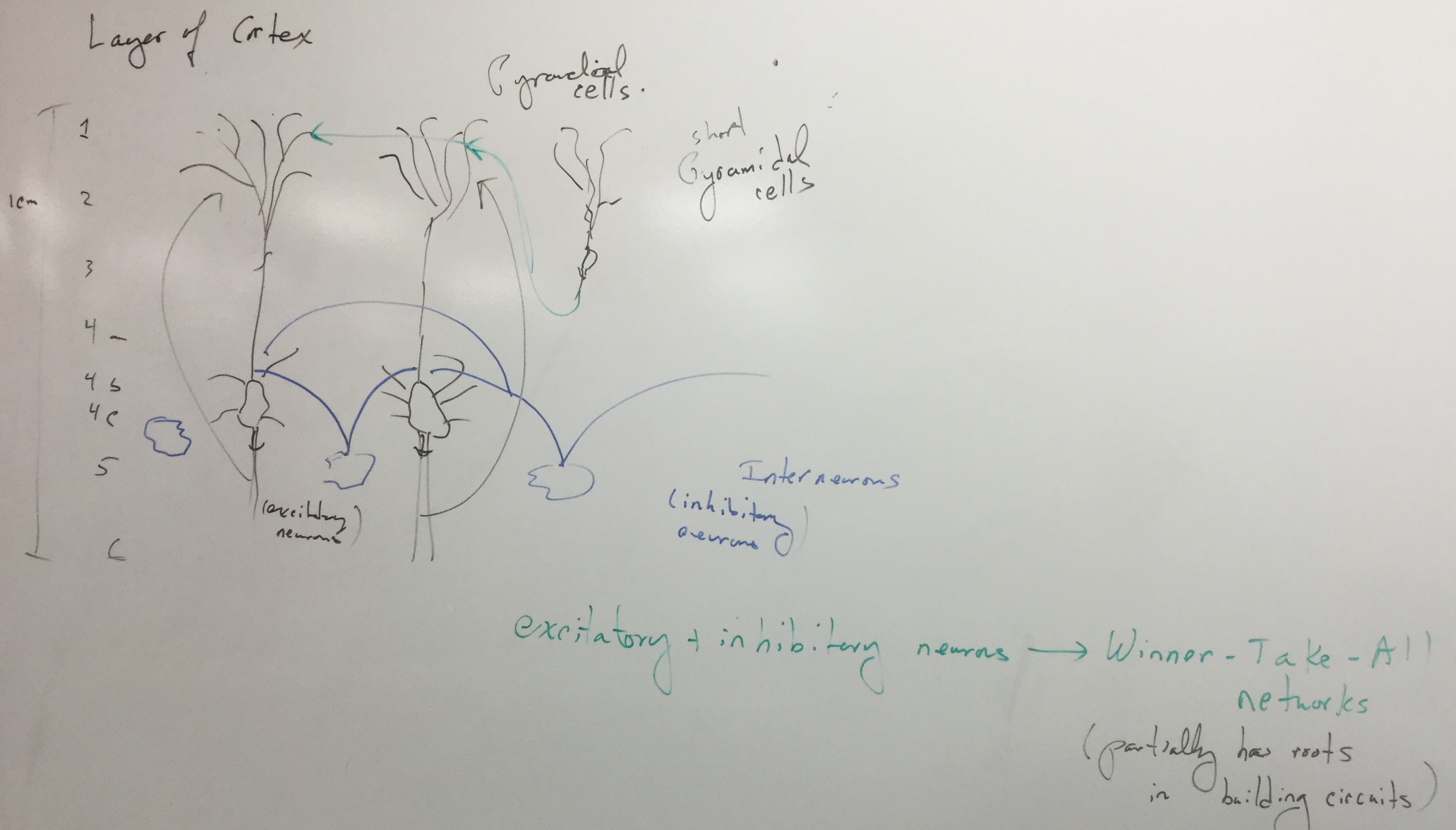
- The winner--take--all (WTA) circuit models a neural network consisting of n excitatory cells and one inhibitory cell. When the excitatory cells are active, they excite the inhibitory cell which in turn inhibits the excitatory cells. The inhibitory cell's activity will increase until it kills off all the excitatory cells except one. If the loop gain is high enough, this excitatory cell will be able to maintain the requisite level of inhibitory cell activity by itself. Naturally, the excitatory cell that survives will be the one with the largest extrinsic input.
- A useful extension of the WTA network is to introduce a pool of inhibitory neurons with local connectivity between them. Then competition occurs over a local region whose extent is determined by how far signals spread among the inhibitory cells. Excitatory cells that are outside this region will not be inhibited much. In these cases, we talk about the locality of these WTA networks.
Project Approach
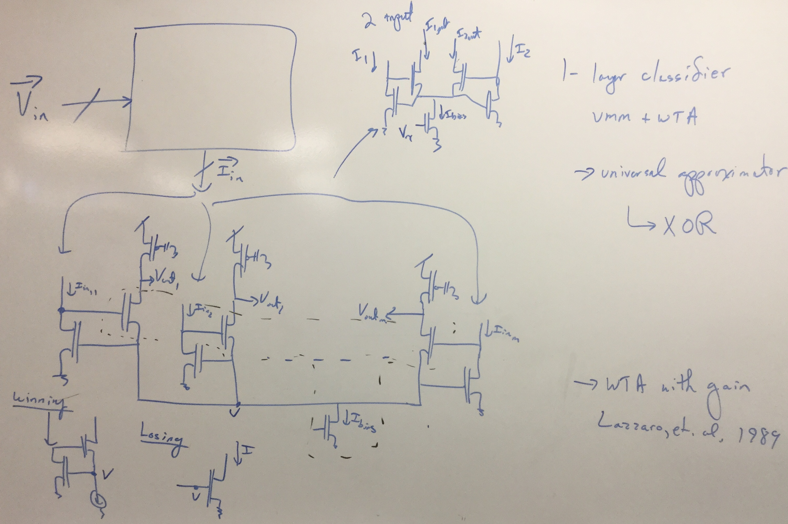
This project will cover the WTA and VMM circuits individually, then combine them to perform classification.Experiment 1: WTA Circuit
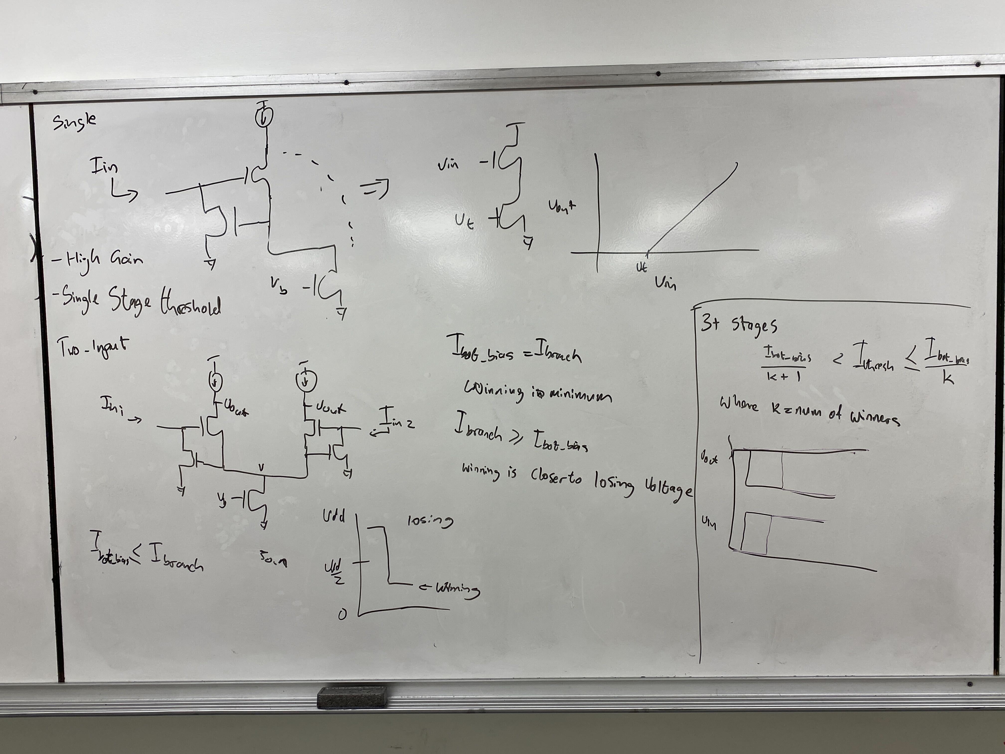
(a) Characterize the gain of a single WTA stage.
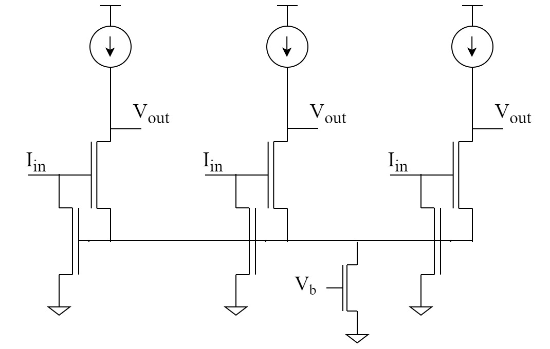
- Set up a two input WTA network as seen in the figure above. Starting Parameters.
- Fix one input at a voltage within the active region (e.g. 1.7 V) and perform a tight sweep using the second input.
- Measure the output of the WTA branch being swept. Calculate the voltage gain.
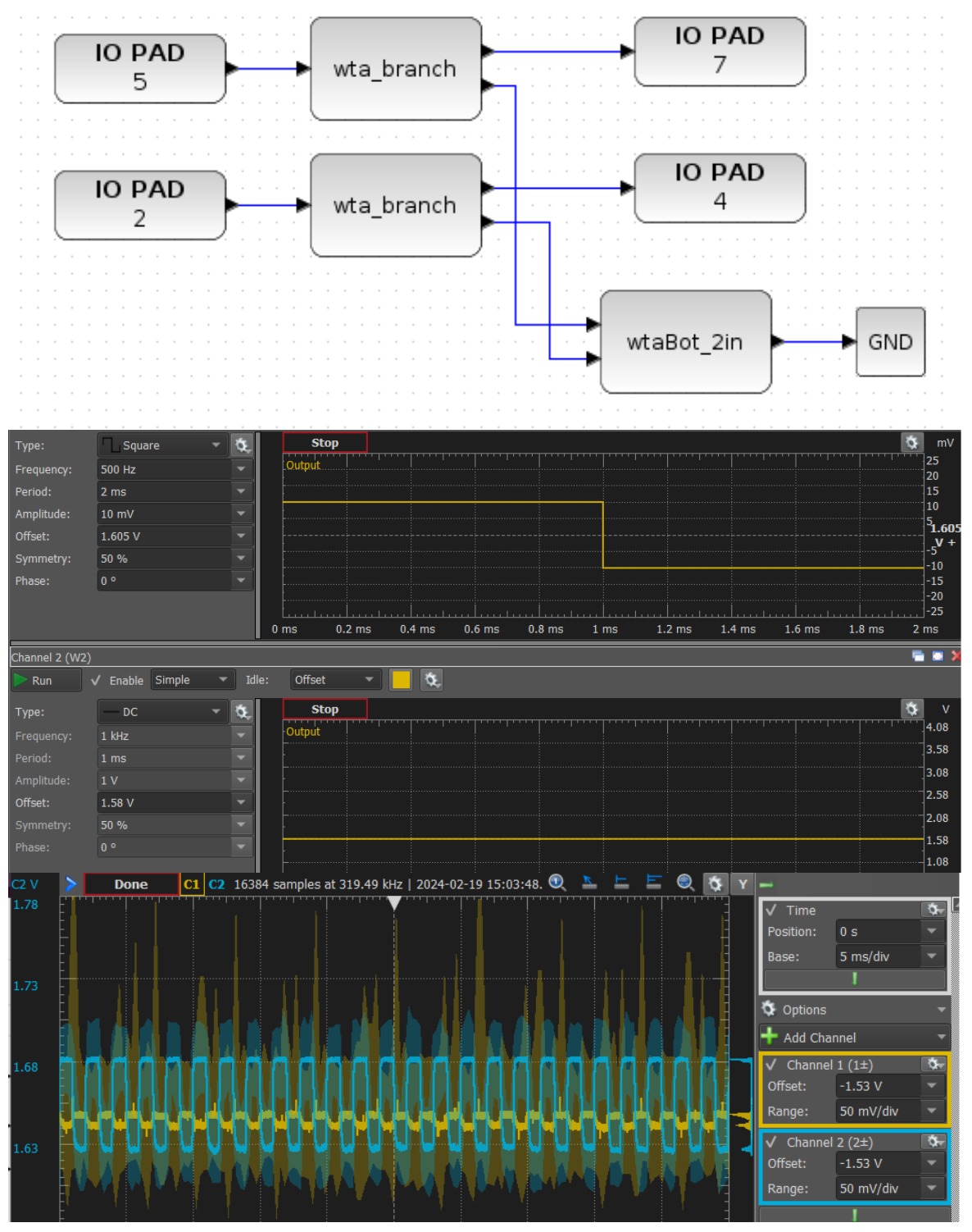
- Apply a step input with ~1.6 V offset and 10 mV amplitude to one input, and plot both output voltages. You should still see the outputs invert.
- Discuss what the effects of threshold mismatch of the transistors could be in this circuit. Did you see any effects in your data?
(b) Measure a 3-Stage (or higher) WTA circuit. This experiment can be done on chip, and offchip data is fine as well.
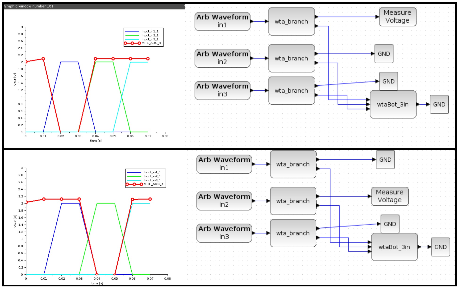
- Set up a three input WTA network as seen in the figure above. Starting Parameters.
- The goal is to show each branch winning independently. Extract your data from the working folder and plot it.
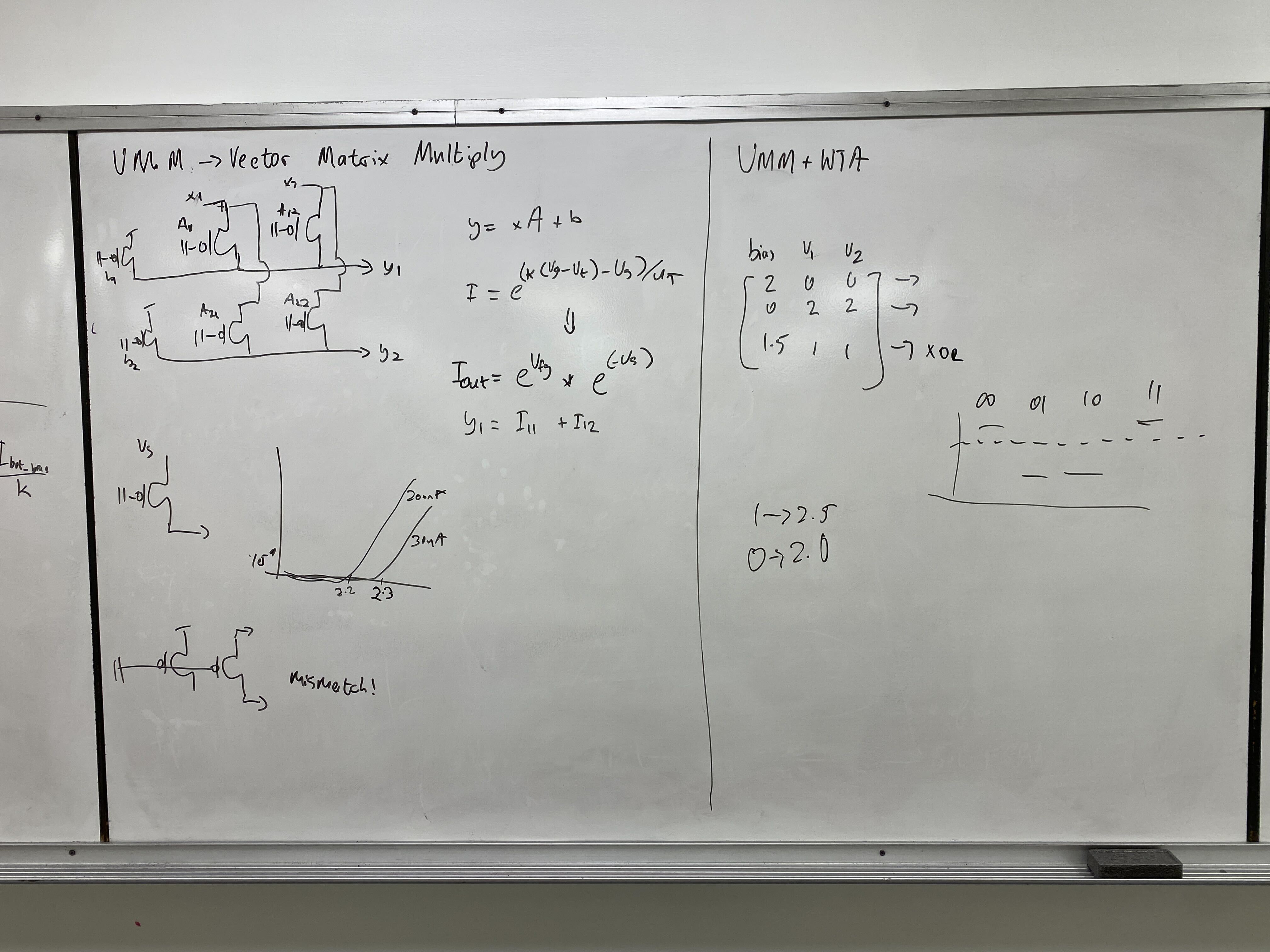
Experiment 2: VMM Circuit
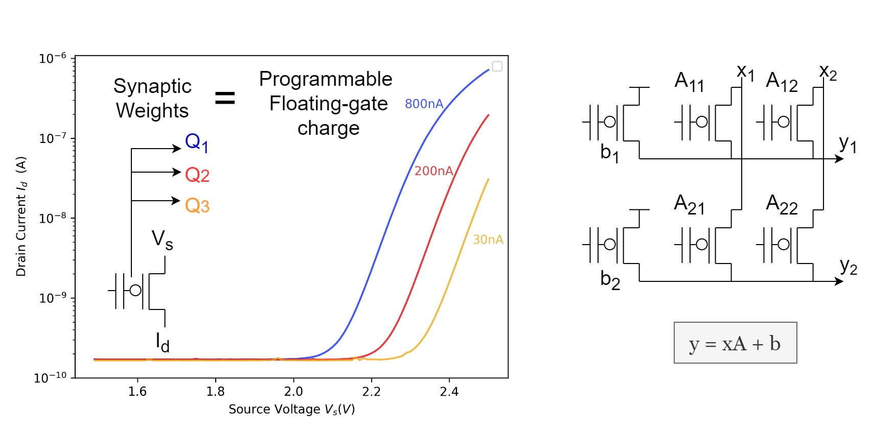
(a) Demonstrate single quadrant analog vector matrix multiplication.
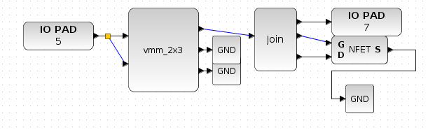
- Program one row of the 'vmm_2x3' block, tie both inputs together to be swept and measure the output over a diode connected nFET. Starting Parameters.
- Plot a voltage vs voltage curve to identify the input range for that particular set of weights.
- Double the weights, sweep the input and plot the new curve.
- Discuss why the weights cause the curves to be different. Furthermore, comment on how your input range changes with the size of the weights.
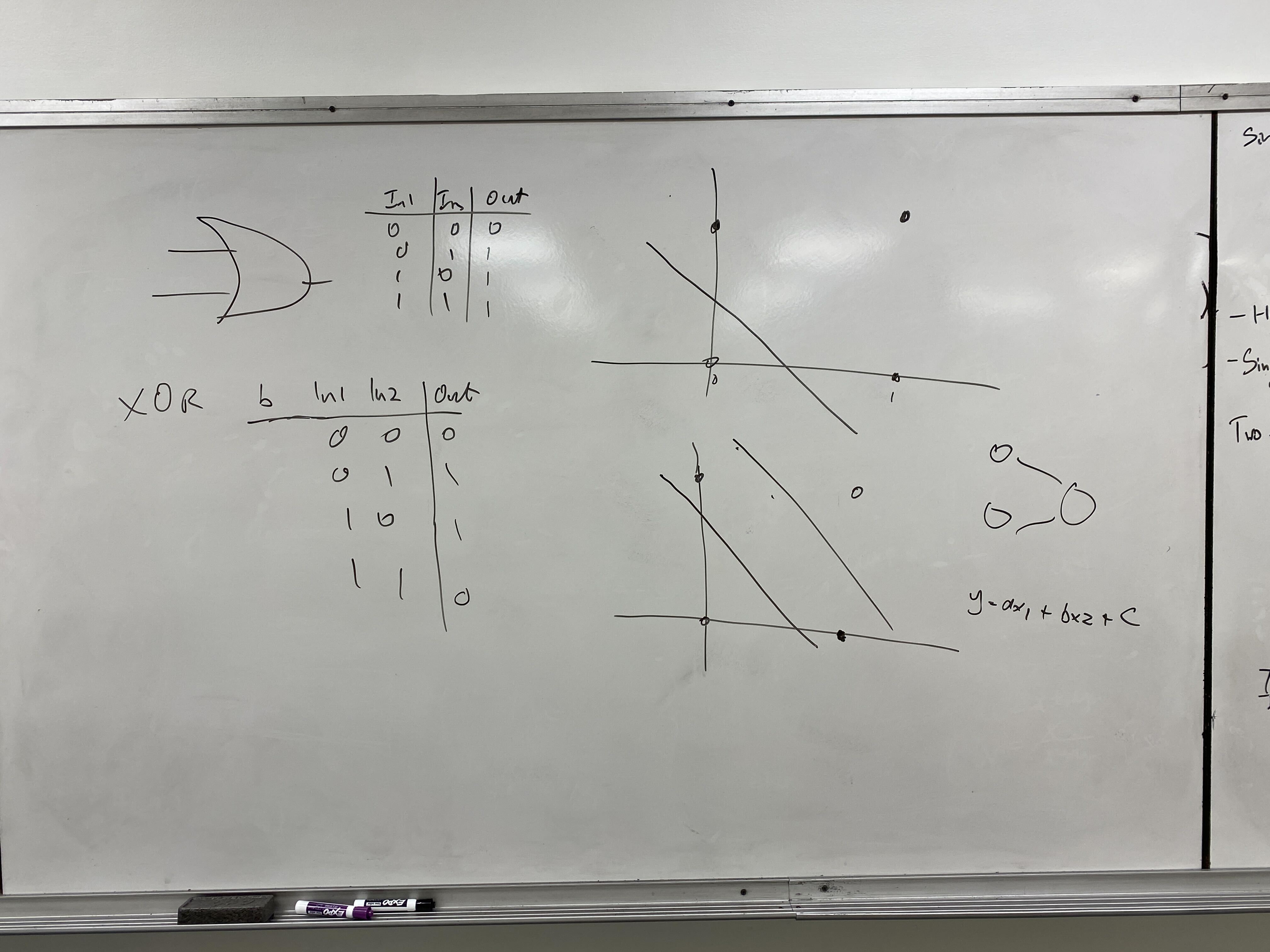
Experiment 3: VMM+WTA XOR Classification
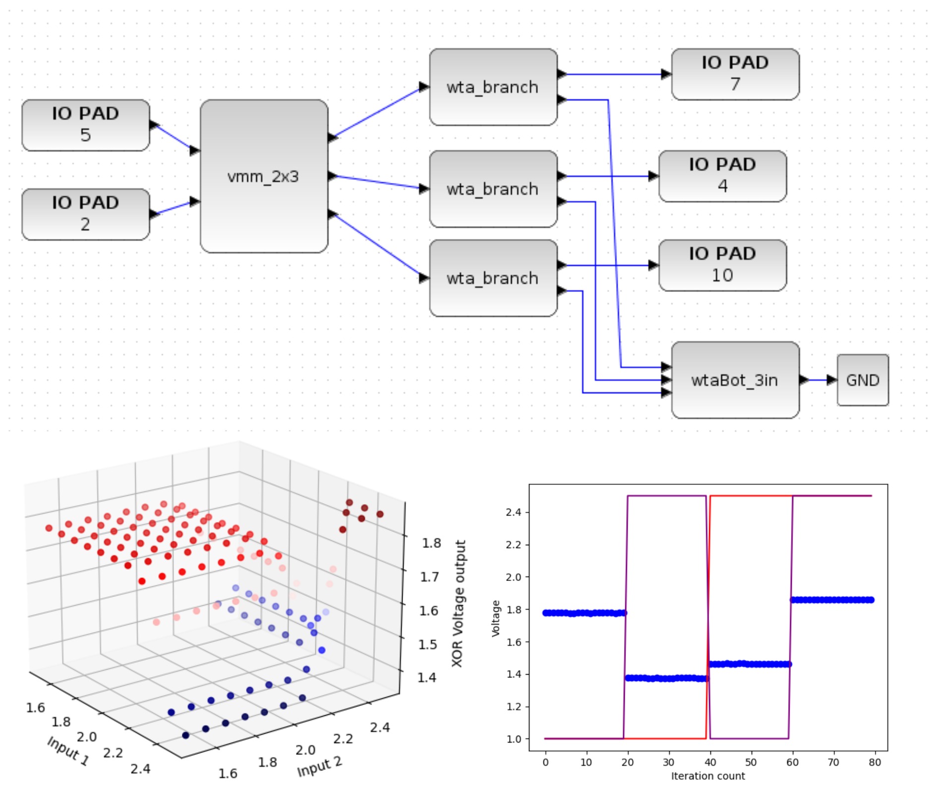
(a) Classify the XOR problem in a single layer with the VMM WTA circuit.
- You only need to submit the time domain waveform in the bottom right in the figure above. Only one output pin is required, the only output pin that was used to plot the data in the figure above was output 4.
- Starting Parameters. Here are tips to tune this circuit
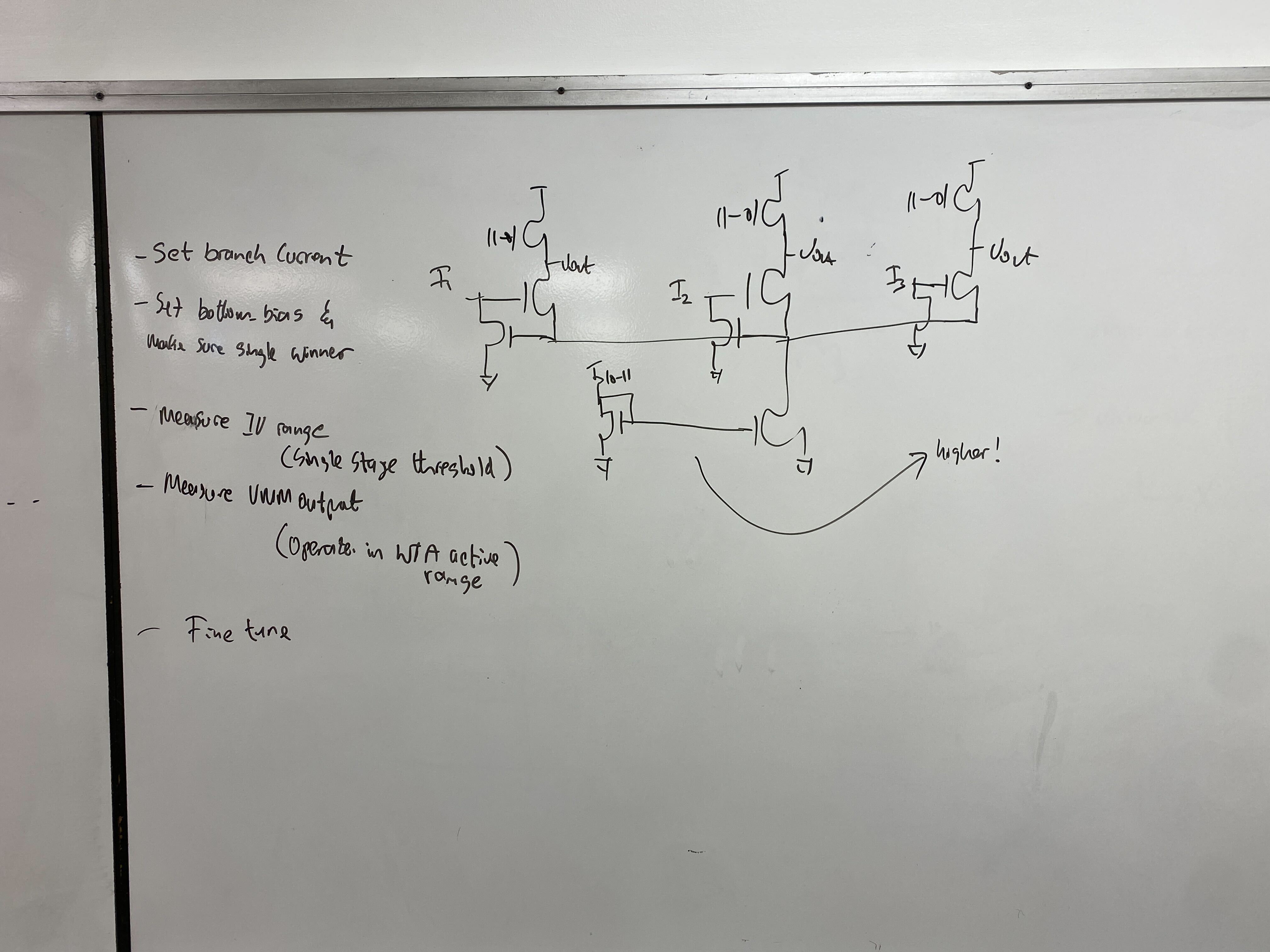
- Ensure all your branch biases in the WTA network match
- Ensure the bottom nFET bias sets enough current both for each branch to win independently and for a single branch to compete and win (2.5 - 5u Range for the current mirror setting the bias voltage).
- Double check that your VMM output voltages are above the single stage threshold voltage and below the maximum WTA input voltage (Generally between 1.4 - 2.2V).