|
This topic is essential as second-order dynamics shows up throughout most
electrical IC and neurobioogical systems.
The bandpass filterbank structure directly models the physics of mammalian cochlea,
the first stage in the neural hearing pathway.
This project directly addresses using Floating-Gate (FG) circuit techniques
in all of our circuit approaches.
Topics
- Parallel Second-Order Sections
- Ladder Filter Approachs
- Building Higher Order Filters
- Floating-gate circuits
Class Schedule and Video Viewing
|
Date
|
Class Topic
|
On-Line Lectures
|
Reading Material
|
White Boards
| |
Jan 23
|
Second-Order
Systems
|
SOS Concepts,
Diff2 SOS,
An SOS LPF,
C-Focused Op-amp Circuit
C-R Op-Amp Example
.
|
Follower Integrator(Chp.9),
Differentiators & Diff2 & HysDiff(Chp.10),
Low-Pass SOS(Chp.11),
|
1,
2,
3,
4,
5,
6,
7,
8,
9
| |
Jan 25
|
Bandpass
Filters
|
C4 SOS,
Gyrator Circuit
SoC FPAA Arch
C4 BPF on SoC FPAA
BPF Test Structure on SoC FPAA
.
|
Classic C4,
|
1,
2,
3,
4,
5,
6,
7,
| |
Jan 30
|
Noise
|
MOSFET noise
Source follower kT/C noise
Bio Cochlea,
Cochlea Mechanical Dynamics,
Human Hearing,
.
|
Transistor noise,
A cochlea Paper
|
1,
2,
3,
4,
5,
6,
7,
8,
| |
Feb 1
|
FG Design
|
Floating-Gate Circuit Intro
Historical FG circuits,
Impact prog. FG --> analog ICs
Physical FG devices,
State Holding Divider,
Charge Summation,
Cap + Amp
|
Modular & FG Analog,
|
1,
2,
3,
4,
|
Please be careful when handling the FPAAs for measurement.
Place the boards on a flat surface, on the foil sheet when measuring
and do not dangle the boards from your PC with the USB cable.
The impedance of your measurement equipment matters,
use high impedance probes with unbuffered pins for the most accurate measurements.
Remember to keep the FPAAs in Van Leer.
Boards not found in lab when we check is a major class violation.
Reading Material
- Paper using FG devices for OTA based
filters
- One compiled (on an FPAA) version of using a small filterbank (C4) for
Speech Processing
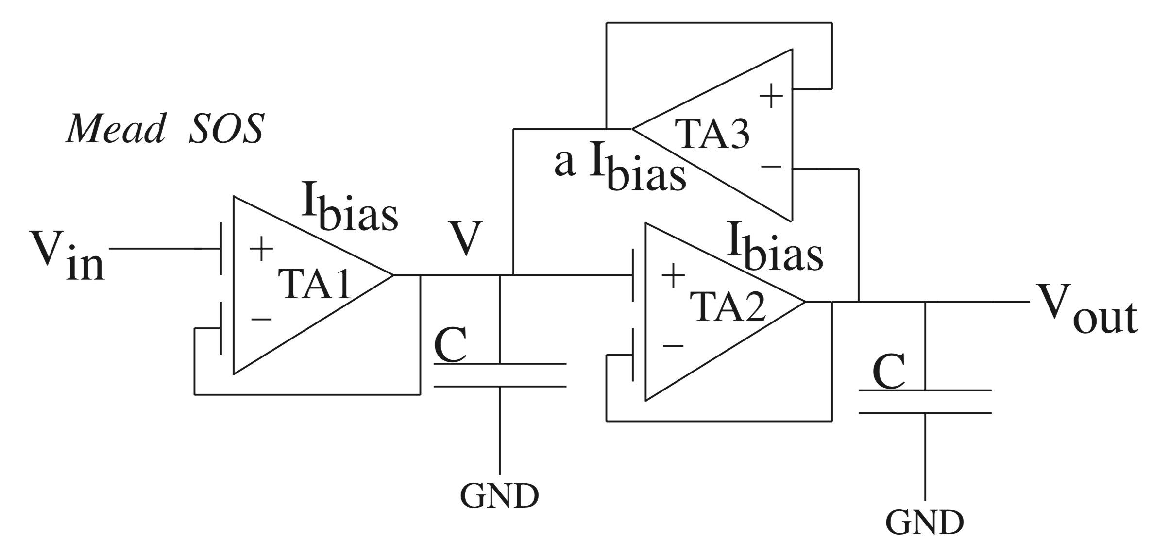
Experiment 1: Second-Order Low Pass Filter: MeadSOS

Figure 1: Mead SOS FPAA implementation using two FG TA elements and one non-FG TA element
The MeadSOS is a classic second-order low pass filter first shown in AVLSI Chapter 11. When coupled with FG devices, the circuit can be tuned, have a large linear range, and have almost zero offset voltage.
MeadSOS Analysis
- Derive the transfer function of the MeadSOS
- Using the transfer function, and assuming an input with frequency 1/t
- Compare a long cascade of second-order sections to a filter bank
- Why would you prefer one over another?
- *Consider transistor variation, stability, and signal delays
MeadSOS Measurements
Using the FPAA, program the MeadSOS to three different Q values (>1) but with the same cutoff frequency
- Measure the step response of all three Q's for a small (50-100mV) input amplitude
- Plot temporal responses on a single graph
- Measure the step response of the largest Q for 2 large input amplitudes (>500 mV)
- Plot the temporal response of the two large steps with the small step on a single graph
- Measure the frequency response of all three Q's for a small input (100mV pp)
- Plot frequency responses on a log-log plot, measure Q
- Measure the frequency response of the highest Q for a large input step
- Plot on a log-log plot
- Comment on any changes from the smaller step
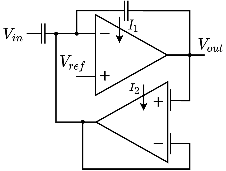
Experiment 2: The C4 Bandpass Filter

Figure 2: C4 FPAA implementation using one FG TA element and one non-FG TA element
The Capacatively Coupled Current Conveyer (C4) is a tunable bandpass filter developed at Georgia Tech.
C4 Measurements
Using the FPAA, program the C4 to three different Q values (>1) but with the same center frequency
- Measure the step response of all three Q's for a small (50-100mV) input amplitude
- Plot temporal responses on a single graph
- Measure the step response of the largest Q for 2 large input amplitudes (>500 mV)
- Plot the temporal response of the two large steps with the small step on a single graph
- Measure the frequency response of all three Q's for a small input (100mV pp)
- Plot frequency responses on a log-log plot, measure Q
- Measure the frequency response of the highest Q for a large input step
- Plot on a log-log plot
- Comment on any changes from the smaller step
Bandpass Filterbank
One of the advantages of the C4 is that the corners of the response are separately tunable from the Q. We can use this to create a bank of bandpass filters, each tunable to a different frequency range.
Demonstrate this functionality by tuning an exponentially spaced bank (4+) of C4 filters
- Plot the frequency response of the C4 bank
- Run a waveform through the bank and show the output waveform
- Comment on how the human ear relates to a bandpass filterbank
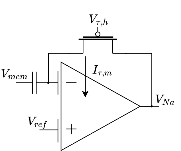
Experiment 3: The Sodium Channel Gating Circuit
Our model for the gating dynamics of a Na channel is a bandpass filter, very similar to the C4. The FPAA model is slightly different from the original, using a TA instead of a common source amplifier.
Na Gating Measurements

Figure 3: NA Gating circuit FPAA implementation using one FG TA element, a pFET/FG pFET, and an explicit capacitor
Program an Na Gating circuit onto the FPAA
- Measure the step response for three different amplitudes
- Measure the frequency response the same three amplitudes
- Comment on the gain at different input steps. Is the change linear?
- Relate your measurements to Hodgkin and Huxley's measurements of the Na channel conductance
|


