Topics
These are the core topics for the first project.
- Basic linear circuit elements
- Basic Circuit Analysis
- Resistive Circuits with independent and dependent sources
- Superposition, Symmetric Circuits
- Thevenin--Norton Equivalents
Project Items
This project primarily gets the students comfortable with measurement and resulting analysis of
resistive circuits.
Part of this lab is that you get familiar with your tools, measuring data, and getting data
to a place where you can analyze it and write it up.
Previous years
lab experiment and good examples lab writeups
(
2019 :
Example a and Example b
)
and
( 2020 ).
I am not saying these writeups were perfect,
and yet they were good examples of the better writeups for that semester.

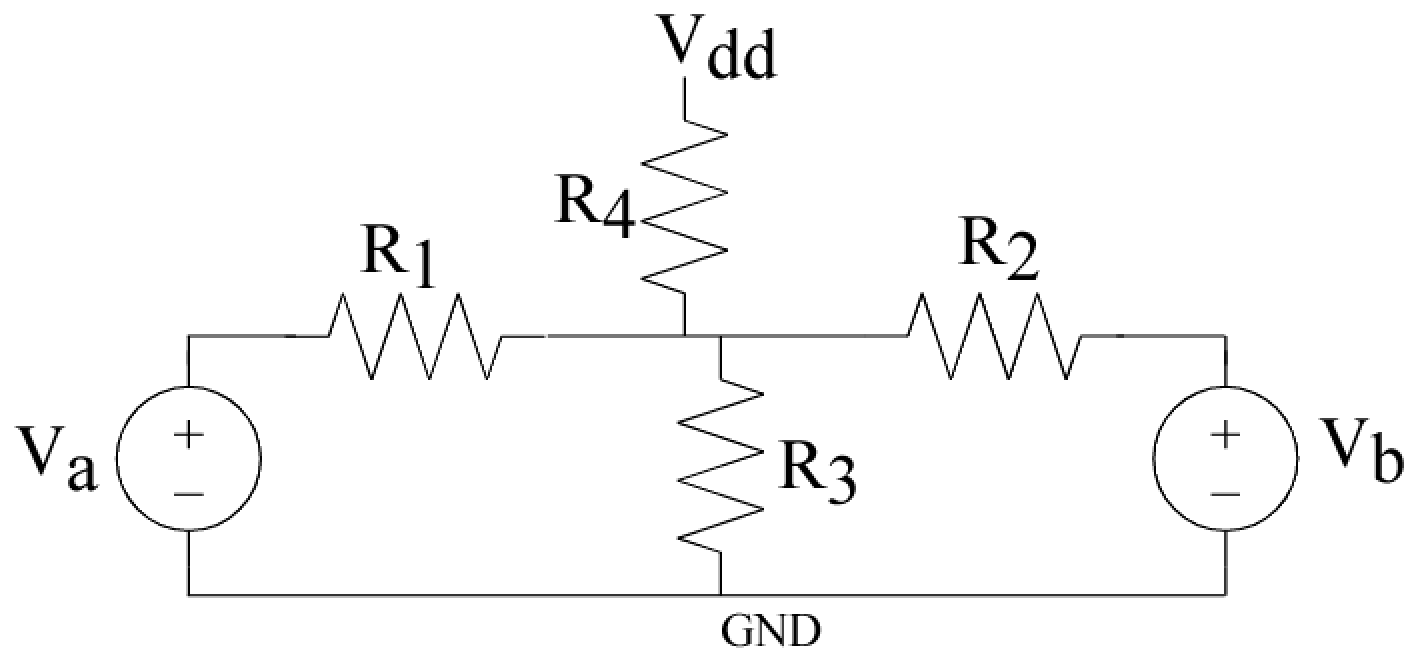
Figure 1:
A resistive circuit with two voltages we can sweep as well as a power supply voltage
to illustrate
the linear behavior of resistive circuits.
- Making resistive dividers with no Vdd resistor :
Using resistors that you have available of the relative size for the resistive voltage divider,
implement the circuit in Fig. 1
with no Vdd resistor,
Use two input signal voltage sources for V1 and V2.
Do not make all of the resistors the same values.
Do a sweep and curve fit for Va when Vb = 0 (GND),
and
do a sweep and curve fit for Vb when Va = 0 (GND).
Compare the values of the slopes to the resulting resistors used in this circuit,
similar to the voltage divider above.
- Making resistive dividers with the Vdd resistor :
Next add the resistor to Vdd (R4),
and repeat the above sweeps and curve fit to extract the slopes and the effective resistances.
- Using the circuit with both current sources : Using this circuit (Fig. 1),
do a sweep and curve fit for V1 when V2 = 0.5V and then 2V,
and do a sweep and curve fit for V2 when V1 = 0.5V and then 2V.
Did the slope change significantly with both voltage signals applied?
What was the new offset voltage, and how does this relate to the circuit network
(circuit analysis is expected for this answer).
How are these results consistent with the fact we are dealing with linear circuit elements?
How could one use superposition to explain these circuit effects?
If the resistors were all the same value, how could you use symmetric circuit techniques for your solution?
|
