|

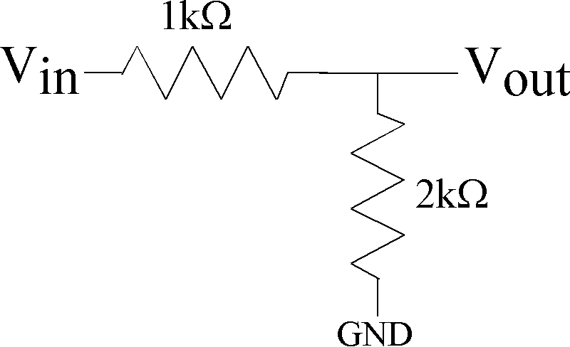
Figure 1: Resistive divider circuit for lab measurement.
|

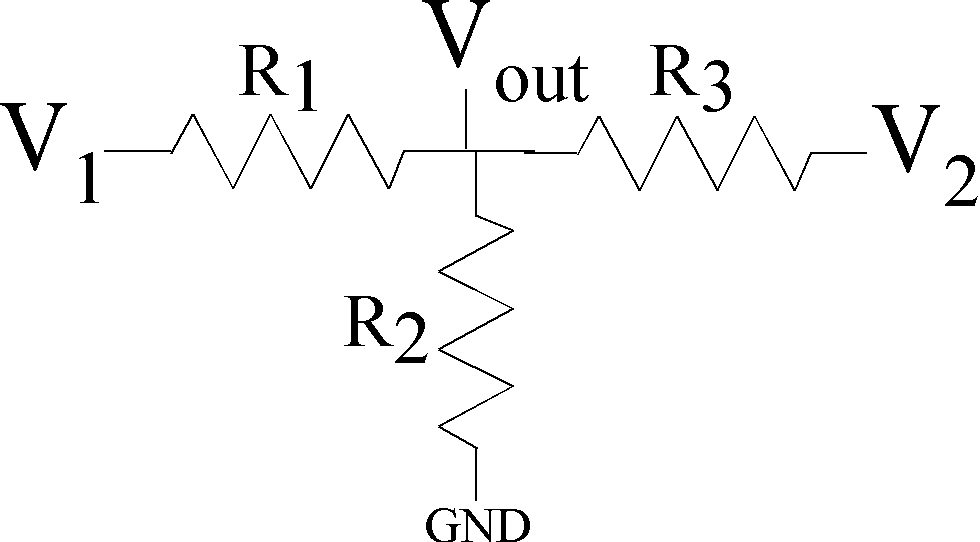
Figure 2: A resistive circuit with two voltages to illustrate
the linear behavior of resistive circuits.
|
- (From 2019 Project)
Set a resistive voltage divider using resistive components (Fig. 1).
If for some reason you have resistor values slightly different than 1kOhm or 2kOhm,
please identify the expected resistor value from the resistor codes.
Sweep the input voltage (Vin) from 0V to 3V or 5V taking roughly 100 points,
and measure the output voltage (Vout).
From your measured data, make a linear curve fit to this data
to find the ratio between R1 and R2 from this data.
You will want to use MATLAB for this operation and plotting,
using the functions polyfit and polyval
(on-line lectures from ECE1371 on this function
are useful to
watch
if you have not used these functions previously.)
The curve fit will give the gain (which you should identify),
the ratio of the output voltage to the input voltage.
I expect a plot with your measured data (say as 'o' points)
and the curve fit on the same plot .
You might measure an offset voltage from the curve fit.
Do you expect an offset theorectically?
You should discuss what
might be causing this value.
Calculate the ideal value of this ratio and compare your results.
After getting these results,
measure the value of R1 and R2
using your data aquisition device or similar device if you have something available.
Compare the resistance values with the indicated tolerances from the resistor codes,
as well as compare the circuit gain and ratio of R1 and R2.
You will want to give a percent deviation from ideal values whereever possible,
as well as other relevant metrics.
- Using resistors that you have available of the relative size for the resistive voltage divider,
implement the circuit in Fig. 2,
where you use two input signal voltage sources for V1 and V2.
Do not make all of the resistors the same values.
Do a sweep and curve fit for V1 when V2 = 0 (GND),
and
do a sweep and curve fit for V2 when V1 = 0 (GND).
Compare the values of the slopes to the resulting resistors used in this circuit,
similar to the voltage divider above.
- Using this circuit (Fig. 2),
do a sweep and curve fit for V1 when V2 = 1V,
and do a sweep and curve fit for V2 when V1 = 1V.
Did the slope change significantly with both voltage signals applied?
What was the new offset voltage, and how does this relate to the circuit network
(circuit analysis is expected for this answer).
How are these results consistent with the fact we are dealing with linear circuit elements?
How could one use superposition to explain these circuit effects?
If the resistors were all the same value, how could you use symmetric circuit techniques for your solution?
|