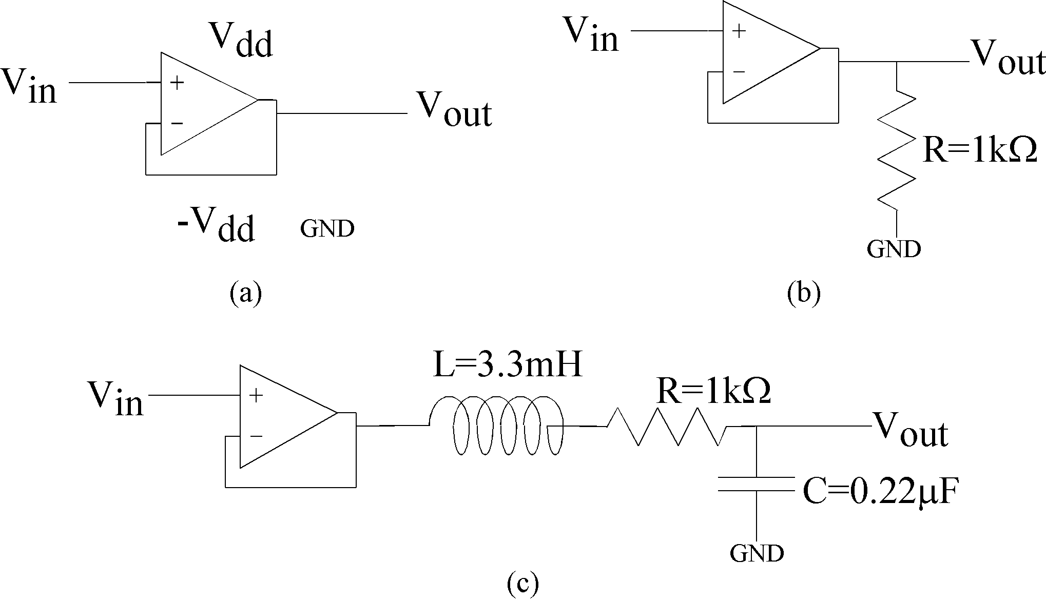
Figure 1: Circuits for lab measurement.
(a) Basic op-amp circuit being used as a follower circuit,
a circuit that has a gain of one.
This circuit isolates the circuit from the sourcing electronics.
(b) Test circuit to measure the follower circuit.
(c) RLC second-order circuit for this laboratory exercise.