|
Topics
- Transistor Biological Channel Model
- Hodgkin-Huxley (HH) Model
- Transistor Channel HH Model
Class Schedule and Video Viewing
|
Date
|
Class Topic
|
On-Line Lectures
|
Reading Material
|
White Boards
| |
Feb 6
|
Transistor
Channel Model
|
Trans-Bio Channels,
|
Transistor Channel Model.
|
1,
2,
3,
4,
5,
6,
7,
| |
Feb 8
|
Hodgkin-Huxley
Si Model
|
HH Trans Model,
HH to FPAA,
|
NN to FPAA
|
1,
2,
3,
4,
5,
6,
| |
Feb 13
|
Further HH
Modeling
|
SoC FPAA HH Example,
Long Talk: HH transistor model
Integ & Fire Neuron,
Adaptive Int & Fire,
|
Integrate & Fire
|
1,
2,
3,
4,
5,
| |
Feb 15
|
Other
Models
|
|
Neuron (Chp. 12)
|
1,
|
Reading Material
- Original work on the HH circuit model discussed in this class comes from
- Original HH model paper
- First circuit implementation of the Integrate and Fire Neuron
- Discussion on analog readout circuitry (useful for neural circuits with many outputs)
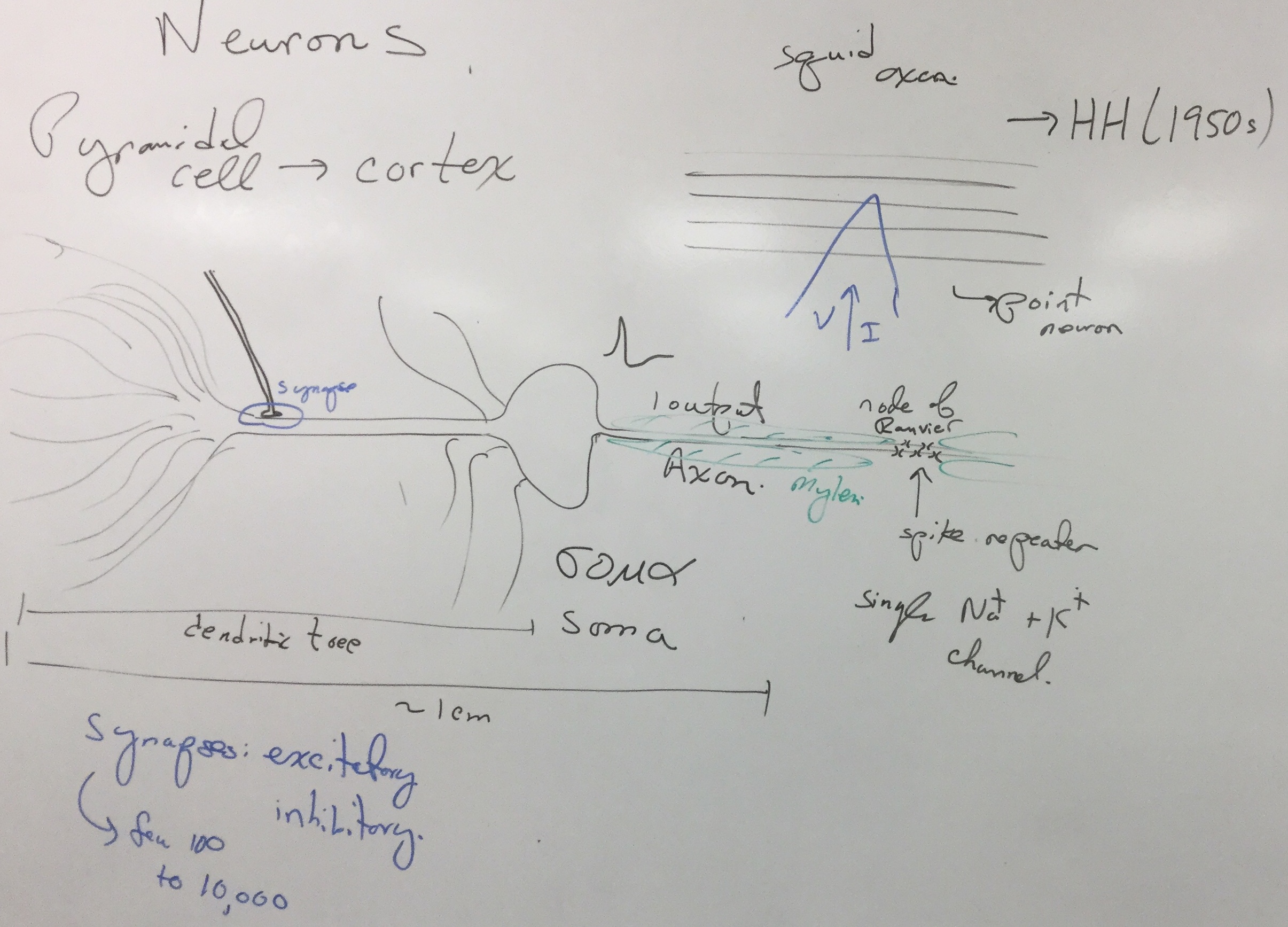
- MIT Intro to Neuroanatomy
Neuron Structure
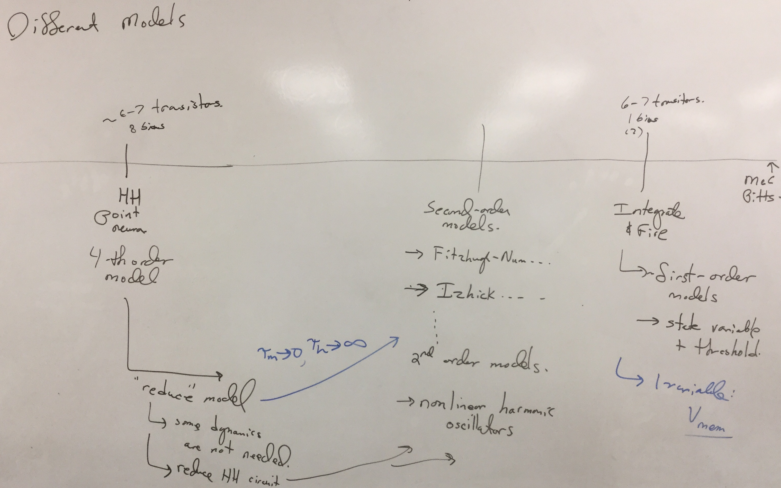
This unit focuses on a biorealistic circuit model for a neuron, combining different concepts from past experiments.
The Passive Channel (Unit 1)
The passive channel forms the basis of the silicon neuron. Recall the IV output and similarity to the voltage controlled barrier across a biolgicaL membrane: These IV dynamics allow biorealism.
Active Gating Circuits (Unit 1 & 2)
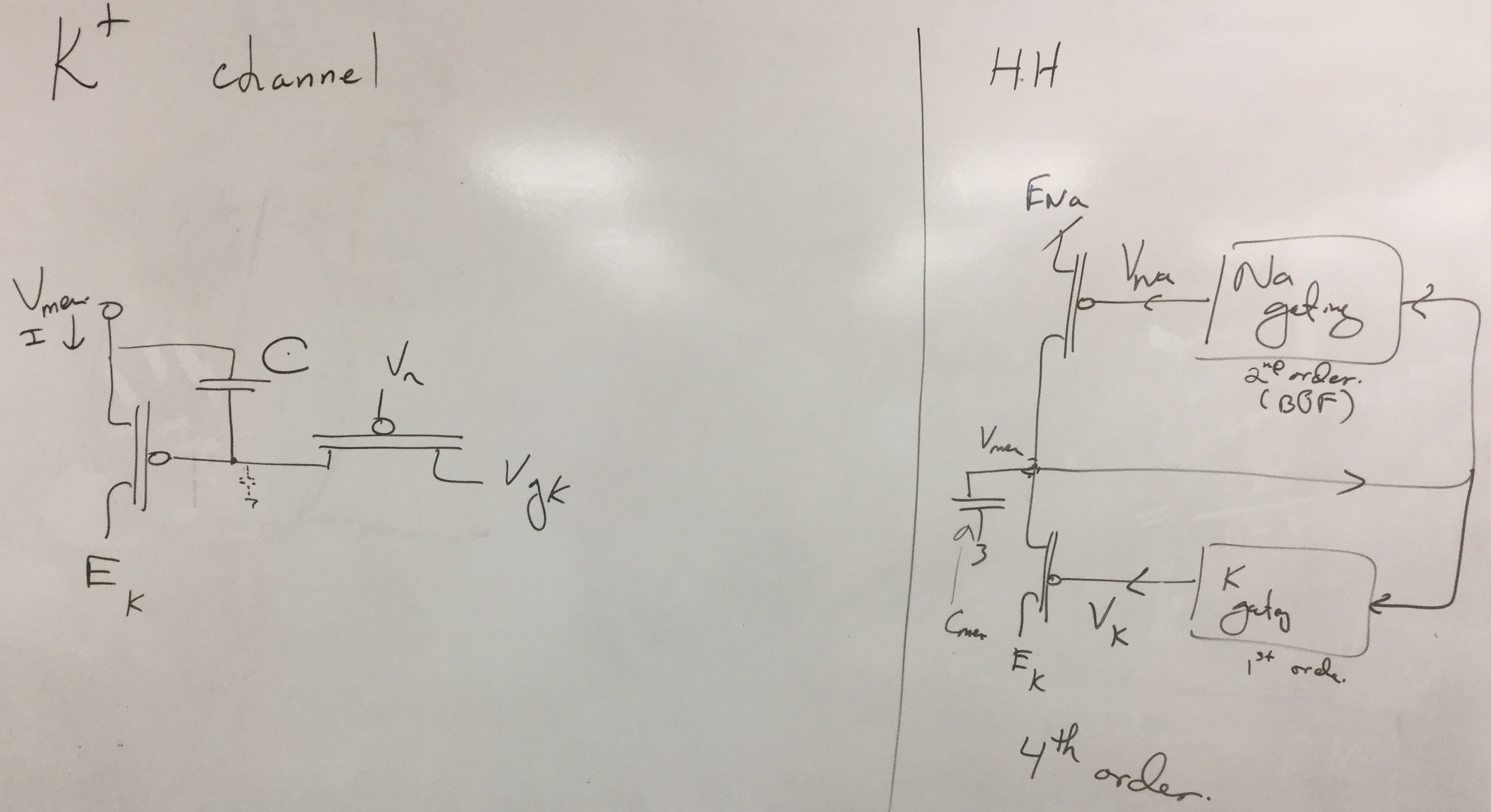
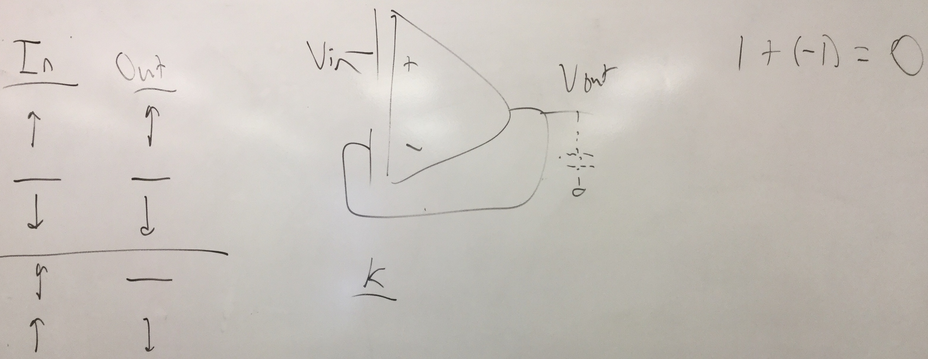
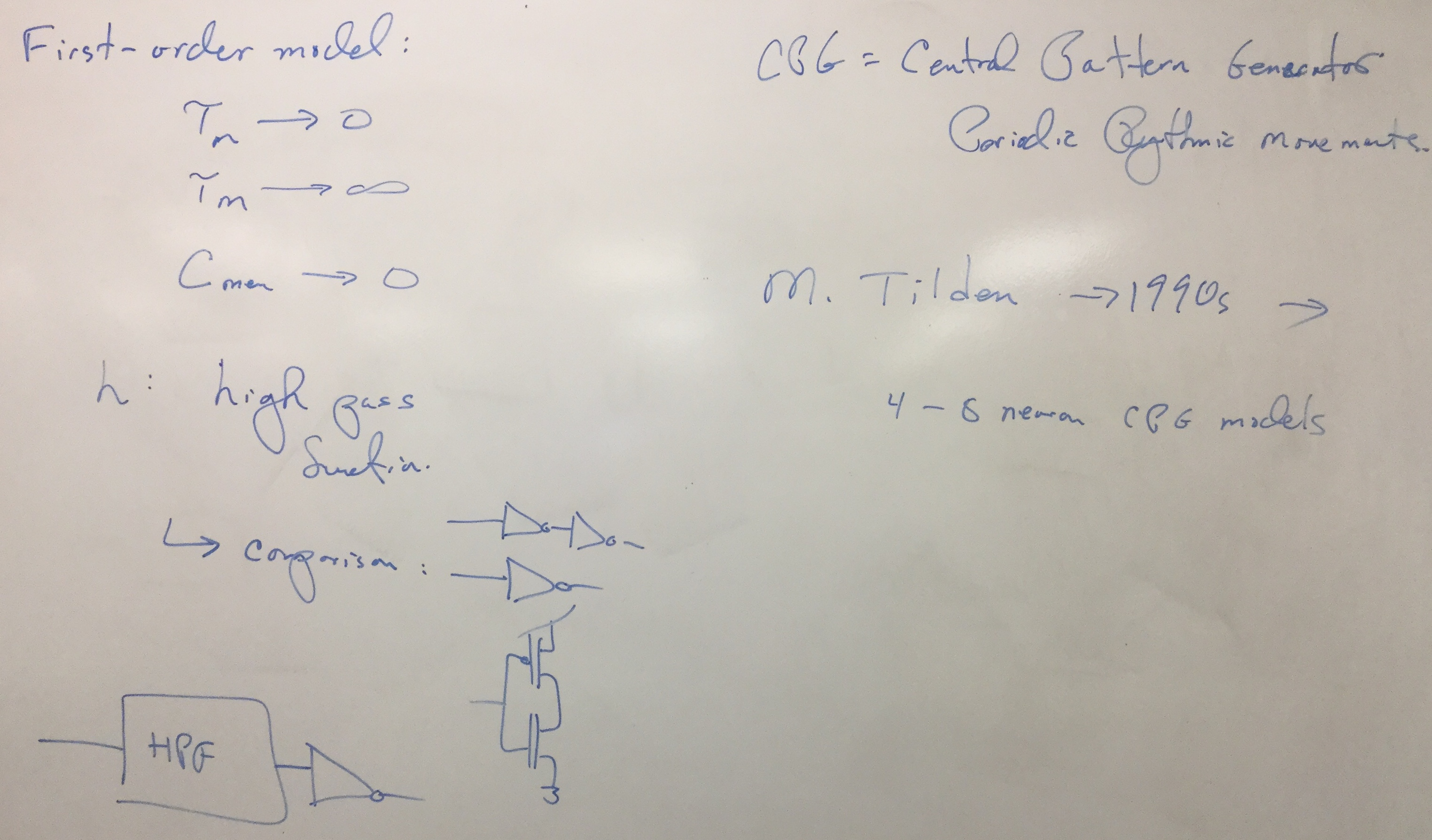
K Gating Circuit (Unit 1):
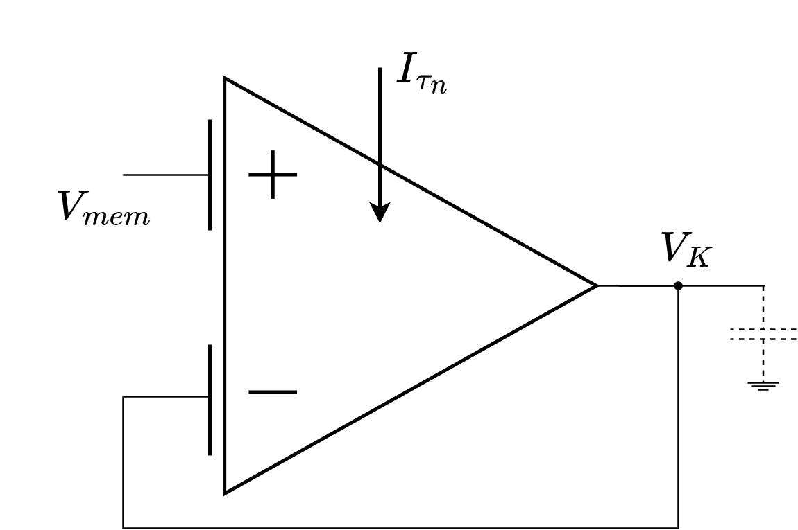
Figure 1: K channel gating circuit, using a Follower-Integrator structure.
The classical K Channel gating circuit has been modified to fit the FPAA structure. Originally the circuit was a high-pass feeding into an inverting (pFET) input, being careful to keep the gain below 1. Parasitic capacitances in the FPAA made a gain above 1 difficult, allowing another structure: A nFET channel with a low-pass gating circuit. This gating circuit is exactly what was measured in Unit 1, a Follower-Integrator, but now with an FG TA that is used to program an offset in the DC level of the output.
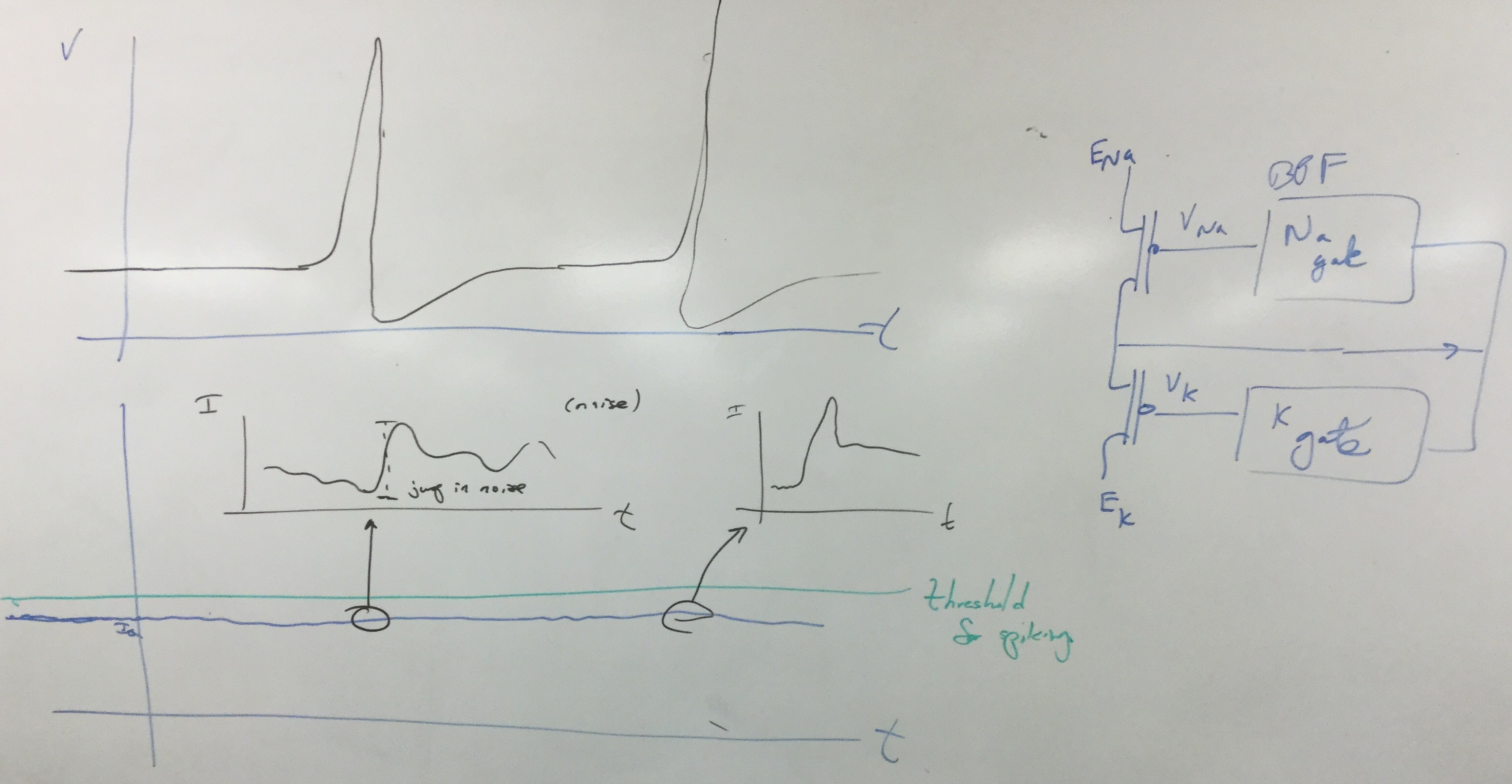
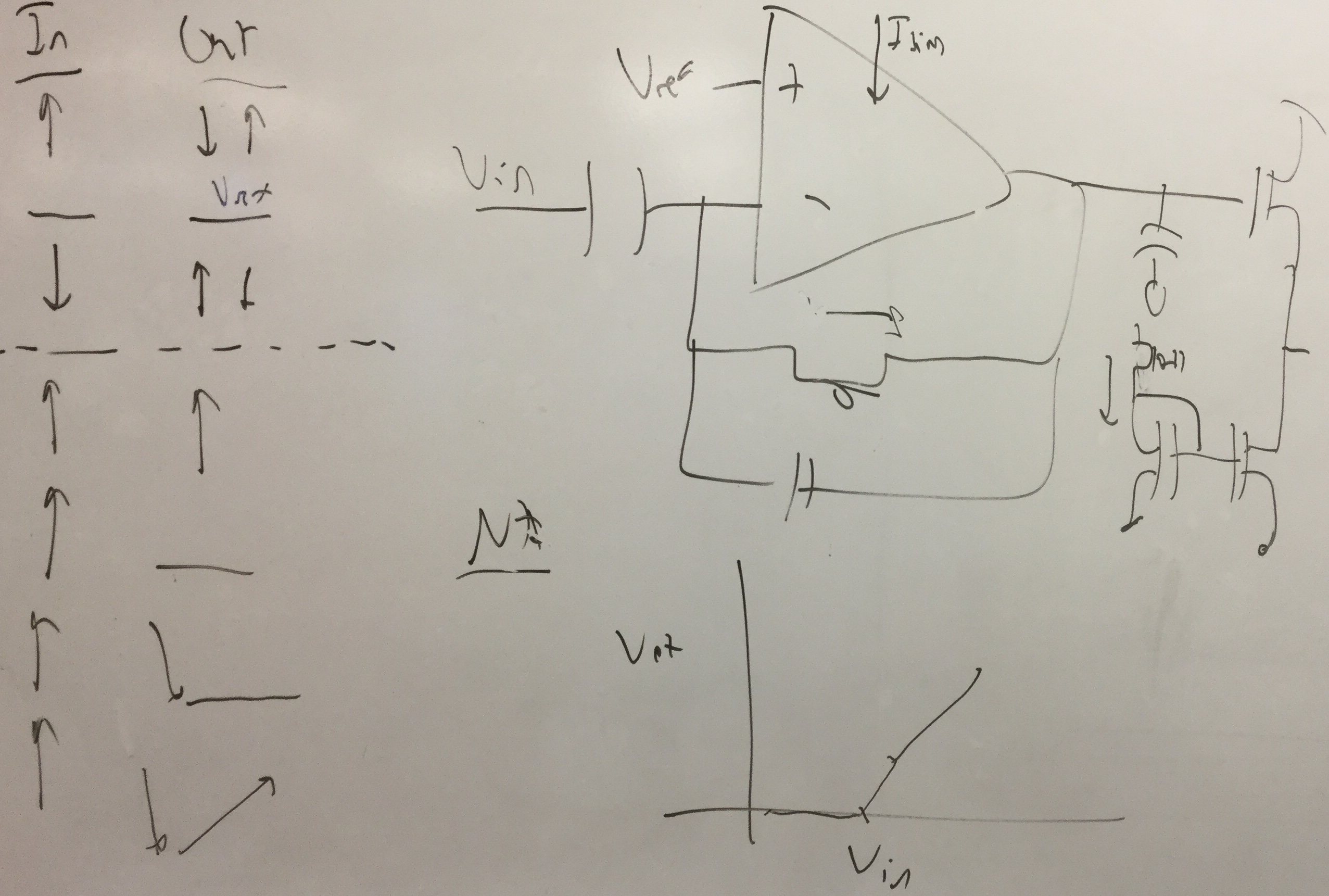
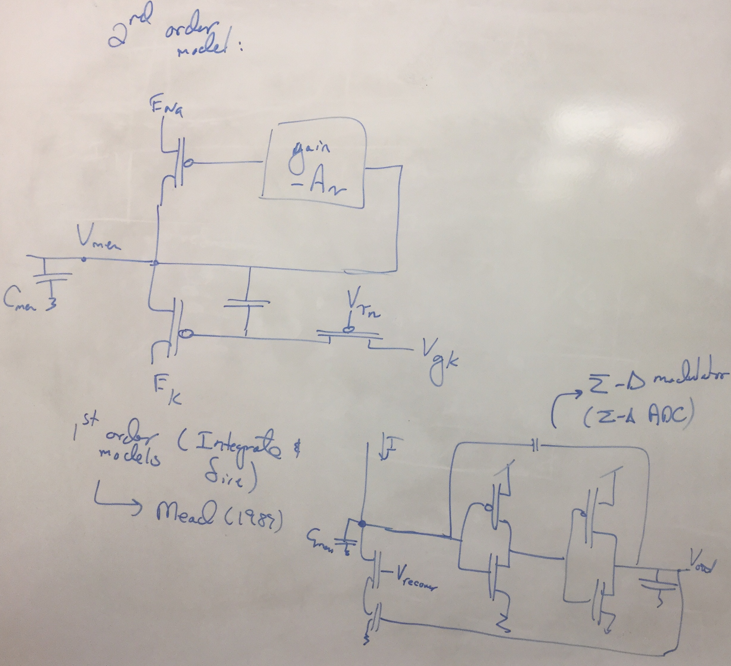
NA Gating Circuit (Unit 2):
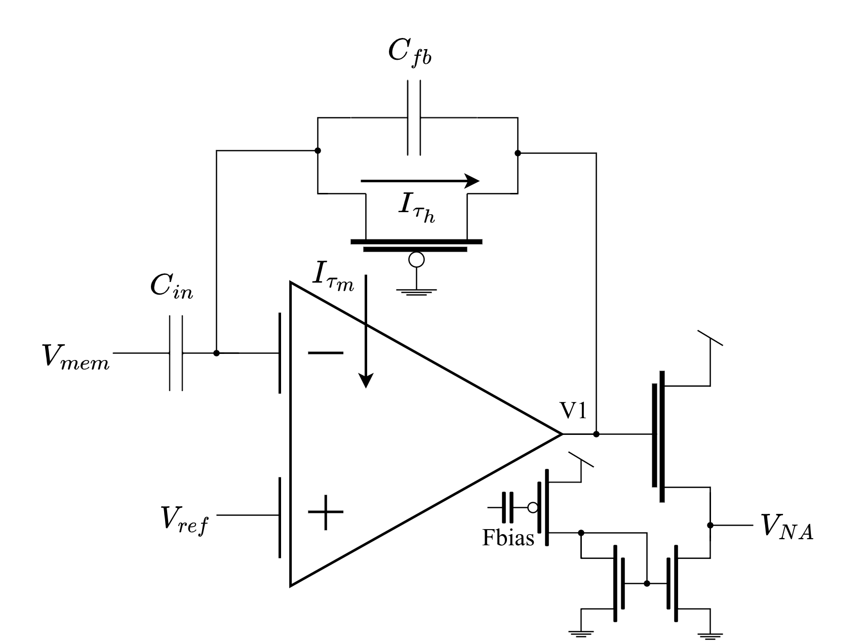
Figure 2: NA channel gating circuit, using a C4-type BPF with a source follower to lower the DC level.
The classical NA Channel gating circuit has been modified to fit the FPAA structure, as discussed in Unit 2. A source follower has been added to the output to lower the DC level, allowing us to use the power rail (GND) as the hard edge that the gain stops at.
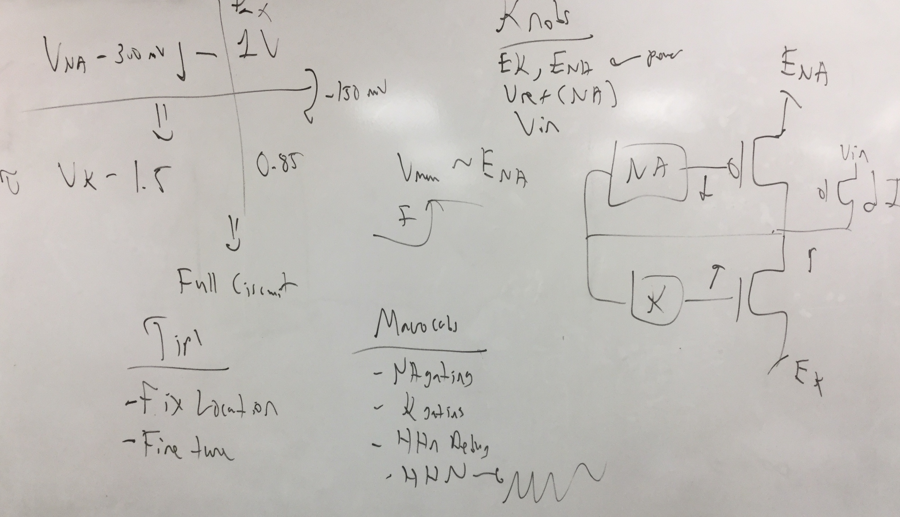
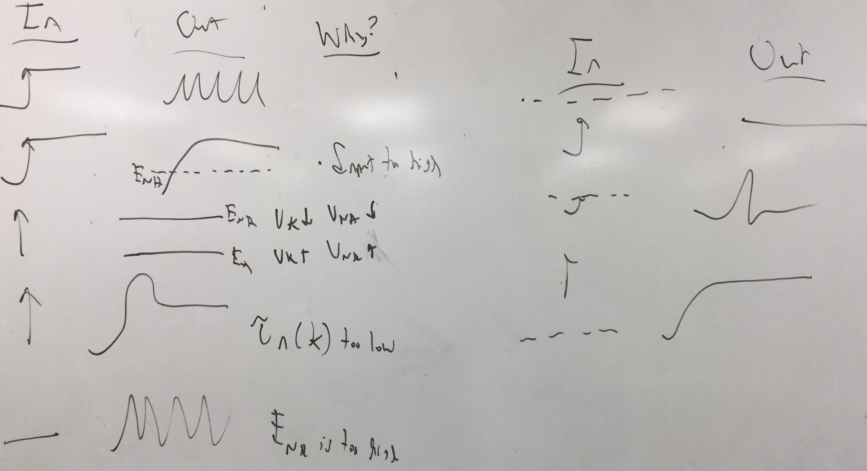
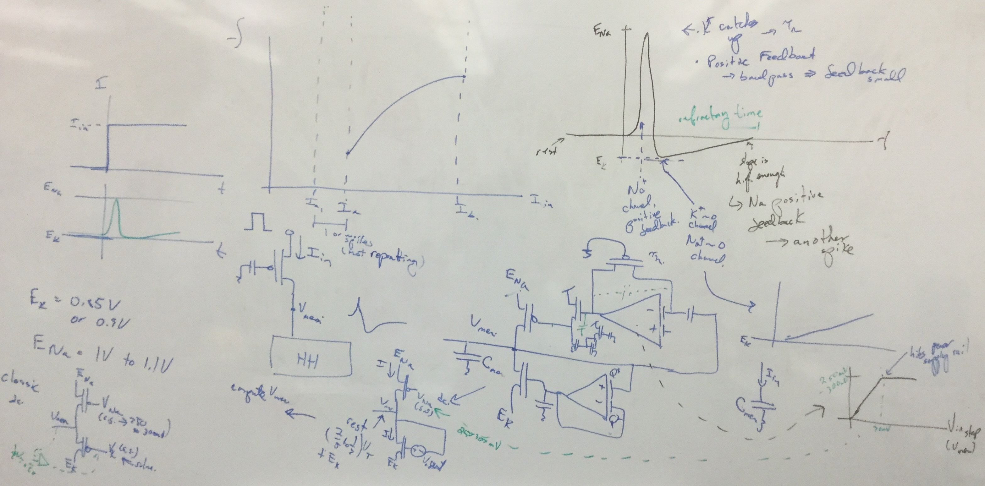
Experiment 1: Silicon Hodgkin-Huxley Neuron
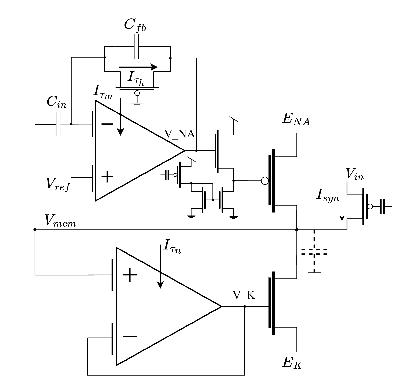
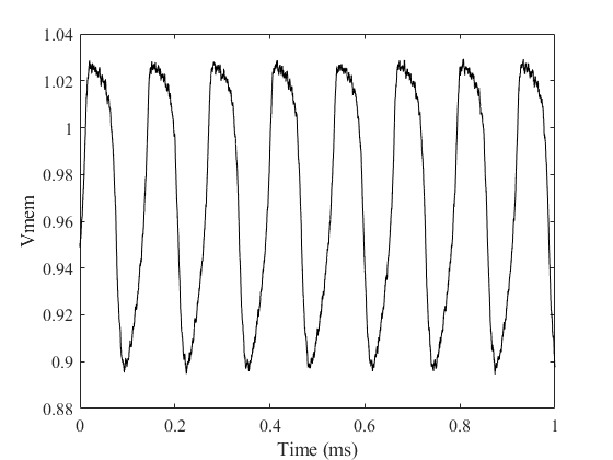
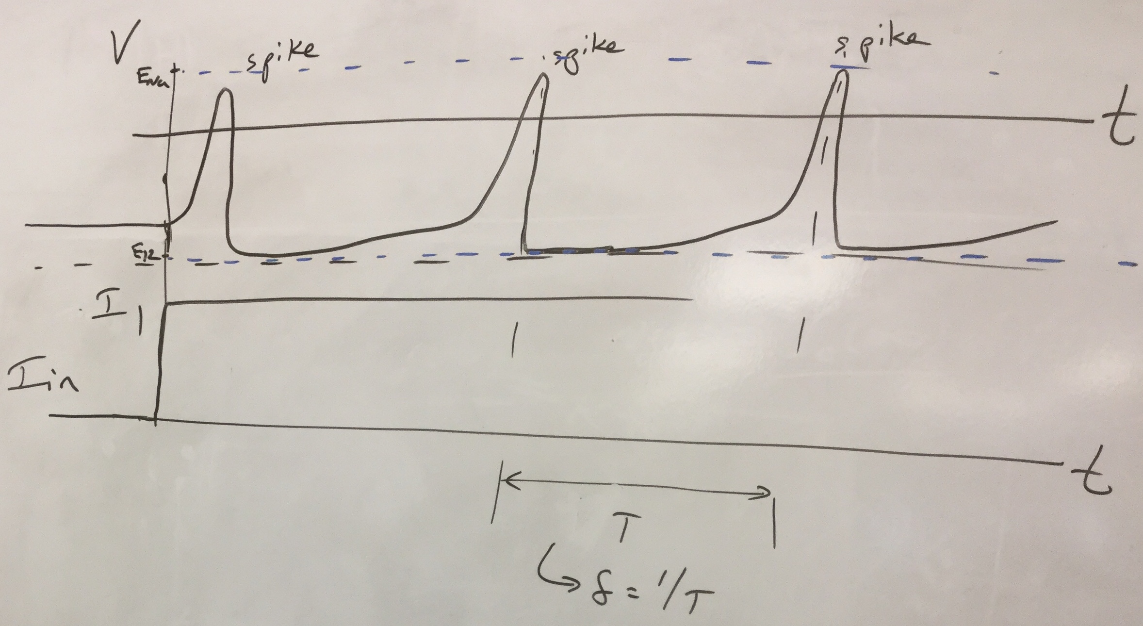
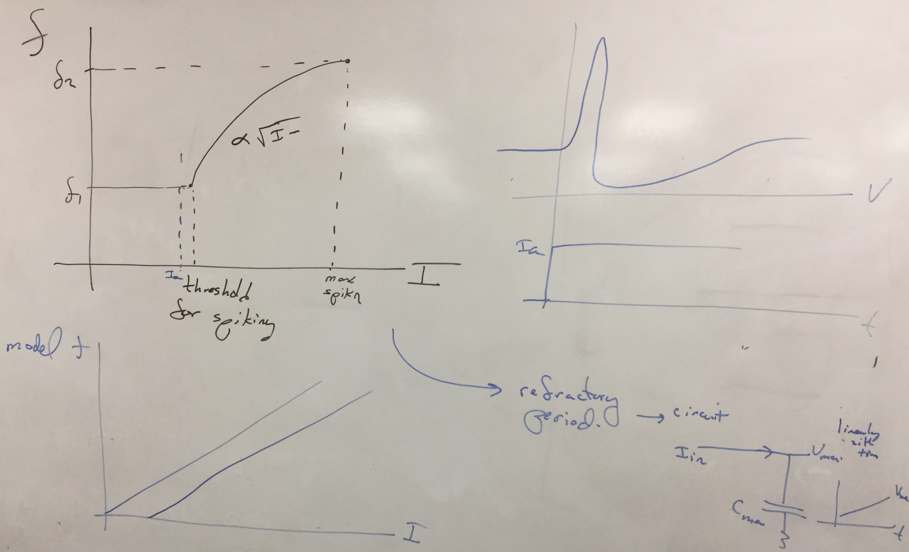
Figure 3: Full FPAA implementation of the silicon HH neuron, and a sample spiking waveform
Build the HH neuron onto the FPAA and measure its output. Some helpful starting parameters .
- Show the neuron output for different input current steps
- Below threshold (no spiking)
- At threshold: 1 spike, and possibly a few more due to noise
- Spiking range (continuous spiking at step)
- Out of range (no spiking)
- Show the neuron output for a DC input in the spiking range
- Show the neuron output for an input ramp
Experiment 2: Silicon Integrate and Fire Neuron
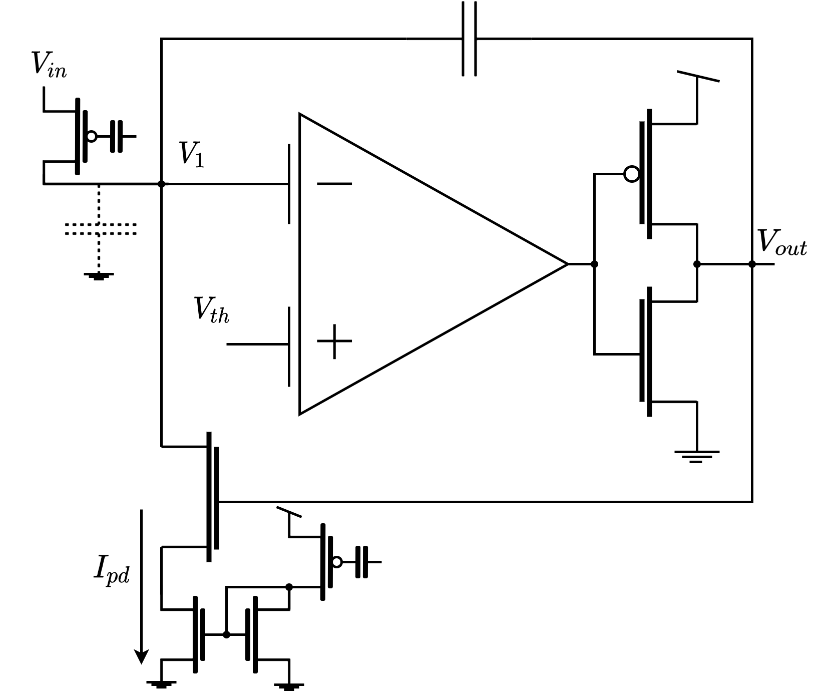
Figure 4: FPAA implementation of the origianl Integrate and Fire neuron.
Build the I&F Neuron from AVLSI onto the FPAA and measure its output
- Show the neuron output for different DC input currents
- Show the neuron output for an input ramp
Experiment 3: Neuron Analysis and Discussion
After examining the behavior of both the HH and IF neuron, compare and contrast their responses
- Which model is more biorealistic?
- Name observed experimental traits to support this
- Compare the area taken by the two neurons
- Consider both FPAA and custom implementations
- Compare the tuning parameters in each neuron
- Why would you use one neuron type over the other?
|