Introduction to Basic VMM Computation and Classifiers VMM +WTA Classification
Course Materials
Taped Lectures
Reading Material
- Paper on Vector-Matrix Multiplication (VMM)
Circuits
compiled into an FPAA structure.
- Paper
on VMM + WTA circuits
showing classification of multiple situations,
showing experimentally the universal approximator behavior.
- As a reminder, the SoC FPAA paper has additional material
that you have read previously.
Summary Notes (.html format)
- Lecture on VMM+WTA:
1 ,
2 ,
3 ,
- Previous Lecture Boards
- VMMwta.pdf file on Tsquare
Project Approach
In this project, we will focus on one type of classifier structure,
the VMM + WTA structure
that elegantly compiles into our FPAA structure.
Small VMM block :
We will look at data from a 2 input (differential) and one output (single-ended)
Vector-Matrix Multiplication (VMM) block.
The structure is similar to the Fig. 5 on page 5 of the SoC FPAA paper,
except we wlll be using two differential inputs.
You would use the built block (which is Macromodelled for this function)
that uses FG devices in the routing fabric for the VMM.
One way to construct this block is to take the 4x4 VMM block as your base element.
The block is assuming single ended inputs, and therefore,
for two differential input signals,
and resulting four-quadrant weights,
you want to use this block.
You will want to put in opposite signals for the positive and negative terminals.
Other approaches are completely reasonable, such as if you took a few floating-gate
pFETs and connected things together, or other switch elements, or other approaches.
And if you decided to take this bock and scan out the values for the 4x4 block,
that would be great and more than meets what is expected.
Also realize that if you put in inputs from the DAC,
which are 7bit,
you have roughly 15-20mV per step.
For the source input VMM with linear operation,
you want to keep differential signals to +.- UT.
So in this case, you might want to have waveforms that are explicitly steps
since the waveforms you will see will be steps.
You can also make an input circuit that divides down the input signals
(make sure to set your dc properly) that will allow more smooth waveforms.
Small VMM +WTA block :
In the demonstration part of your GUI is a VMM + WTA block.
You should copy the definition (you want to keep the working structure there),
and run a number of cases.
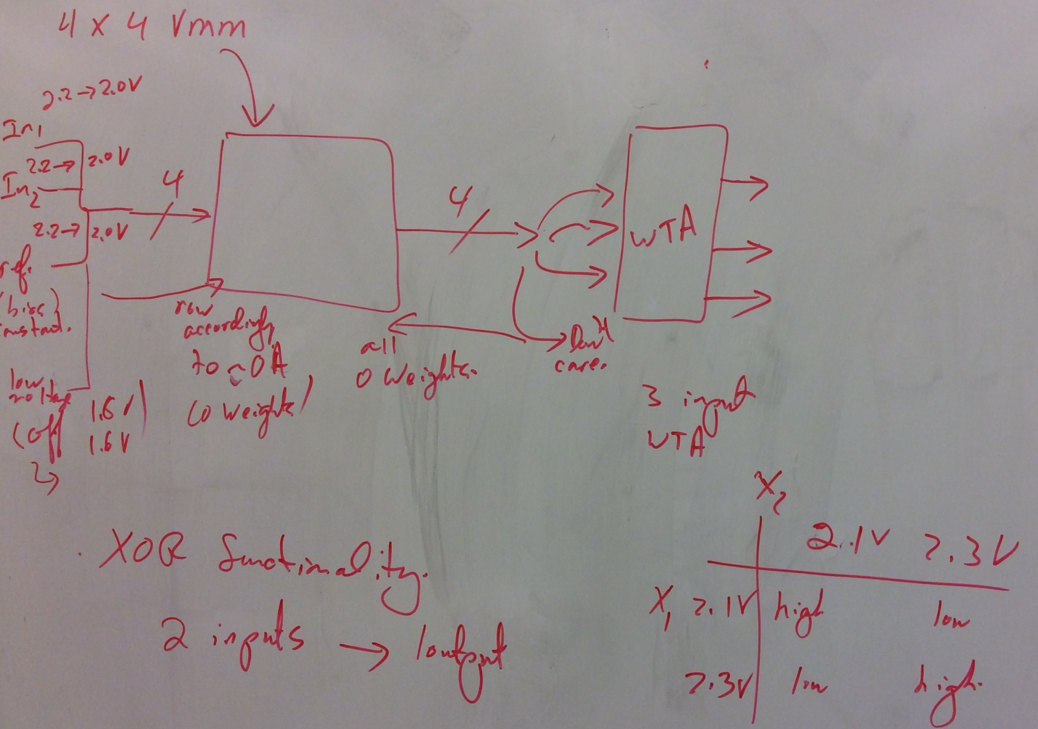
- You actually have starting weights for performing an XOR function.
You see an example on Fig. 7, page 6, of the SoC FPAA paper.
You should run this case, convincing your audience that
it performs as expected.
This first case is entirely to get you familier with the system,
while demonstrating a critical classifier case.
- You should modify the program weights for different functions,
which one should include a traditional hyperplane classification.
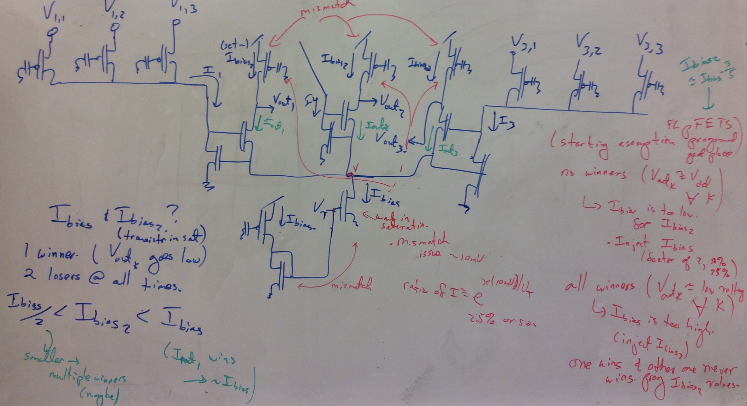
- Your core VMM + WTA block has 4 potential inputs to use,
but was programmed as a single winner WTA block.
Reprogram the WTA block to allow two winners and
show the resulting case.
Remember, that will require programming the pFET current
sources that are acting like a comparitor element
to be saturated at a lower current.
For one winner, you would want a level of roughly half the bias current.
For two winners, you would want a level of roughly 1/3 the bias current.
Feel free to experiment with different cases,
since you can program each of these FG pFET devices are programmed independantly.
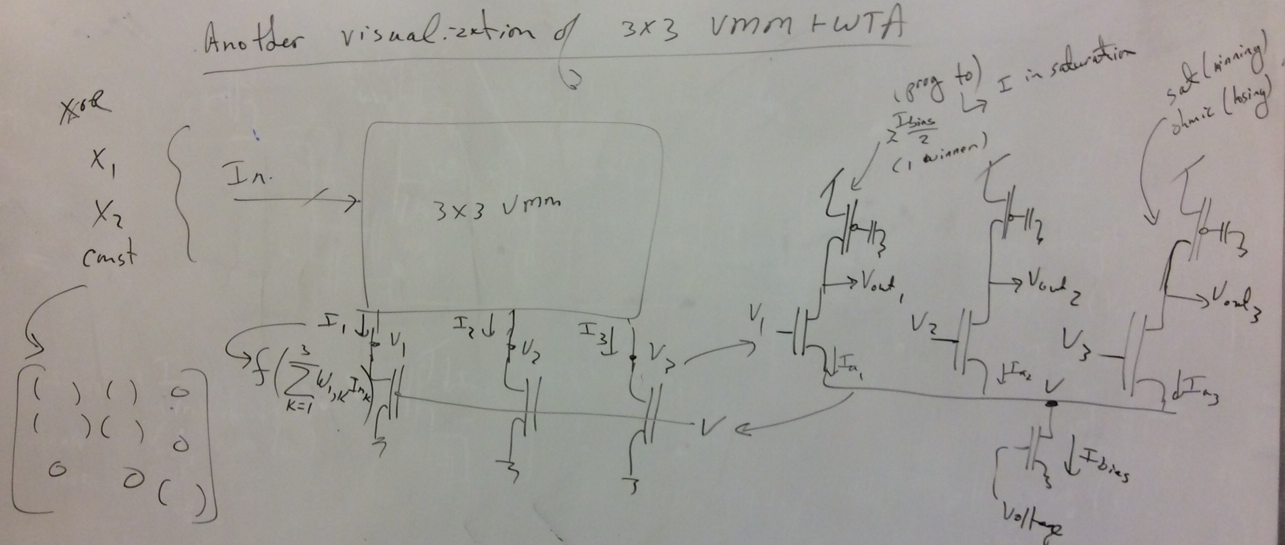
Large VMM+WTA block :
In this case, you will want to use blocks for the larger VMM + WTA that
can get past 4 inputs (actually up to 12 inputs).
After the last section, it probably is obvious one can make general
hyperplanes, but in this case,
we want to show the XOR behavior,
considered n-parity,
to see the resulting universal approximator behavior.
You should compile a structure for a 4 input, 4-parity (you may use more inputs)
function, and show the resulting behavior following the circuit approach.