Unit 4: Introduction to Nonlinear Circuit Topics
Topics
- Nonlinear Circuit Elements (e.g. Diodes)
- How Current Sources are Built (e.g. MOSFET Transistors)
- Basic ideas using these circuits
These discussions will be helpful if you take further classes in
circuits or semiconductor devices (e.g. ECE 3040, ECE3400).
Class Schedule, Topics, Taped Lectures
The particular taped lectures should be watched before class session.
My photographs of the lecture boards will be posted soon after all lectures are finished.
Slides from the on-line lectures:
pdf
Reading
The material is important, but not necessary for completing the project.
- Chapter 2 Material :
Basics of Device Physics.
This chapter is the easiest discussion on basic device physics for electronics.
- Chapter 3 Material : Subthreshold Transistor Physics.
This chapter is the easiest and clearest discussion on
transistor physics for electronics.
Project Items
The focus of this project is on diode elements,
in particular LED diode elements,
elements that emit light when they are sufficiently forward biased.
This project primarily gets the students comfortable with
next level circuit development.
These approaches will involve nonlinear circuit elements.
|
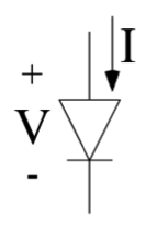
Figure 1: p-n junction diode elements.
(a) Basic diode circuit element.
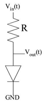
(b) Basic diode--Resistor circuit element.
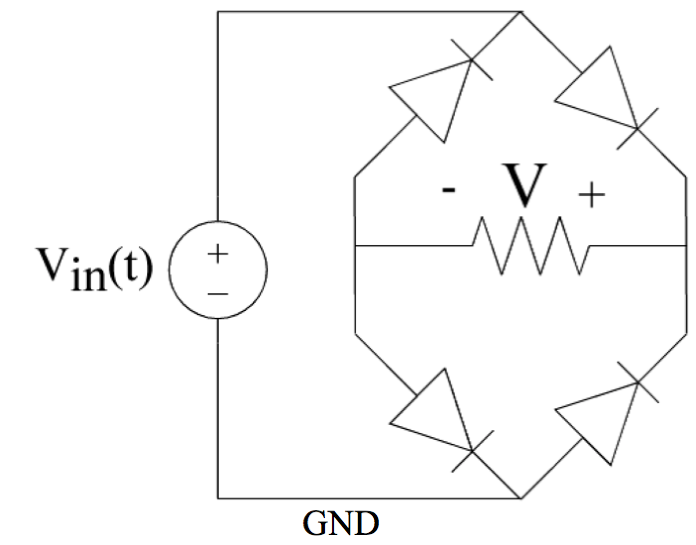
Full-wave rectifier circuit using LED Diodes for lab measurement.
(a) A circuit with 4-diodes and a resistive load.
With a low-frequency signal (e.g. 1Hz), you should be able to see the LEDs
alternatively flashing.
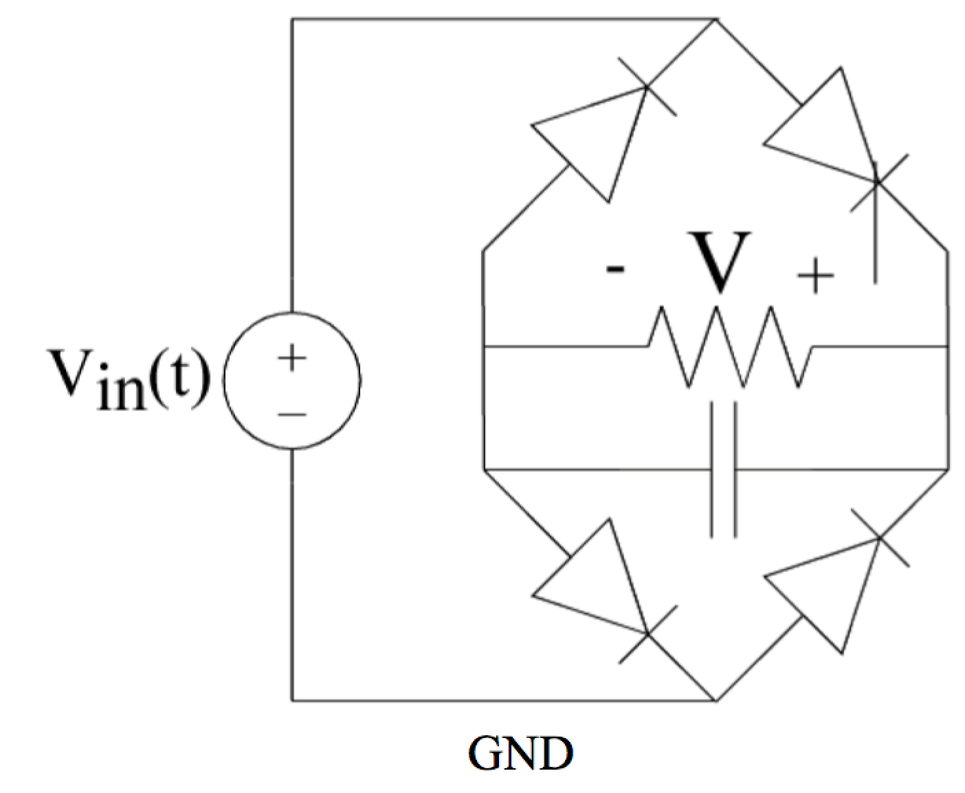
(b) A circuit with 4-diodes and an RC load to filter the output signal.
|
This project focuses on using an LED pn-junction diode (Fig. 1a).
LED Diode Characterization :
Set up the circuit in Fig. 1b and sweep the input voltage (Vin)
from 0 to 5V.
Take a red LED and put a series resistor between 200Ohms and 1KOhm
(1kOhm recommended).
Plot the output voltage (Vout) versus input voltage
for the Resistor--Diode Circuit (Fig. 1b).
Calculate the current through the Diode,
which is the same as the current through the resistor,
and make a plot of the current.
There should be a place where the current is roughly linear with voltage.
Curve fit for those values and relate them to the two devices.
Repeat this circuit for a green LED with a similar series resistor.
Include the two curves (Green LED and Red LED) on the same plot for
voltage and for extracted current.
Using a sinusoidal signal generator (e.g. from your data aquisition device),
put a 1Hz square wave from 5V to GND for the red LED,
and an alternating 1Hz square wave from 5V to GND for the green LED.
A working set of blinking LED lights is often considered the starting point for many experiments.
One might ask why do we have these resistors?
It limits the current.
Your task is to analyze these circuits.
For example,
how do the circuits look when we have 0V, 1V, and 5V across these two elements?
Also, which LED appears brighter to you?
Is that equivalent to the amount of current going through the device?
Full-wave rectifier using LEDs :
Build the full wave rectifier circuit (Fig. 1c).
Set up the circuit in Fig. 1c using two green LEDs, and two red LEDs,
in alternating positions.
Start with circuit without the capacitor (Fig. 1c),
and apply a 1Hz sinusoidal input starting at 5V peak-to-peak.
You might need to go to a 10V peak-to-peak signal.
Might want to buffer the input to have sufficient drive where possible.
Including a photo of your circuit operation would be appropriate.
You are allowed to send a link to a short video of the blinking LEDs from a public location, or send such a short video clip as part of your submission.
Then increase the input frequency between 1kHz and 10kHz.
Take a measurement of the voltage across the resistor.
Then take a measurement when you include a capacitance that mostly
filters out the response; choose an appropriate R-C timeconstant (Fig. 1d).
This circuit shows a classic conversion between
AC power and
a constant DC power supply.
An earlier version of this lab material based from an ECE 3710 material
(pdf).