Linear Circuits with State Variables
Previous Laboratory Experiment, Spring 2019
This project primarily gets the students comfortable with measurement and resulting analysis of
time-domain (Resistor-Capacitor) circuits.
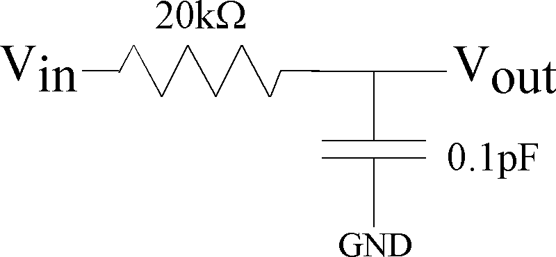
Figure 1: First-order Resistor--Capacitor Circuit for lab measurement.
- Set up the First-Order RC circuit that you find in Fig. 1.
If you do a simple sweep of the input voltage vs. output voltage,
you will notice that the output voltage should approximately equal the input voltage.
The input voltage can be swept for this measurement between 0 and 3V or 5V.
Curve fit this value, and discuss any differences.
- Perform a step response. This means you have a square wave input and look at the resulting output voltage.
Put in an input step between 0.5V and 1.5V. You have a dc voltage of 1V.
Analytically solve for the RC timeconstant,
as well as use your experimental data to experimentally measure the RC timeconstant.
You will perform a curve fit for the resulting time constant,
a curve fit to the exponentially decreasing and exponentially increasing data.
Do the two time-constant values agree?
You need to include a plot of the measured data with curve fits for the time-constant of the measured data.
- Frequency response for this circuit.
Use your device function to do a frequency sweep.
the device inputs a single frequency and measures the result.
Compare your measured frequency response to your expected result.
- Change resistor, change capacitor value.
Both analytically predict the response and measure
the time-domain response and frequency response.
Compare the analytical values with the devices used.
You will want the step response results and time-constant results
efficiently plotted in your report.
You will want a single plot of the two frequency responses.
- Older documentation and problem assignments .
You don't have to complete any of these items explicitly,
although they might be helpful for what is required by this assignment, as well as
some documentation on creating these measurements.